
Instruction Manual

6
© 2013 Nor-Lake, Inc 07/13 Rev. F 132617
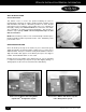
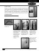
ERECTION DIAGRAM
The erection diagram, as furnished with each walk-in, is a
detailed plan that illustrates the placement of every wall, corner,
ceiling and floor panel that comprises a complete, individual
walk-in.
All sections used to construct your walk-in are marked with
a specific part number on the section, corresponding with its
location on the erection diagram.
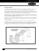
If the walk-in is floorless, then a diagram showing the vinyl
screed (floor sealer) arrangement is provided.
The vinyl screed combines the capability of retaining the wall
panels in place while providing the inner and outer cove at the
junction of the walls and the building floor (a requirement
of Standard No. 7 of the National Sanitation Foundation
(NSF).
IMPORTANT! Do not attempt to erect a floorless walk-in FREEZER on an existing building floor that has not been
specially prepared and adequately insulated for below freezing storage temperatures!
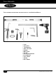
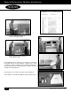
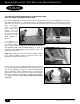
eRecTion diaGRam
• Nor-Lake Inspection Label and panel
specific part number.
The erection diagram for all installations clearly shows the
direction of the male and female formed profile of every wall
panel and every corner panel.
Erection Diagram