
Installation Guide


READ PRIOR TO ATTEMPTING INSTALLATION
ALWAYS TURN OFF MAIN POWER BEFORE INSTALLATION
INSTALLATION SHOULD BE CARRIED OUT BY YOUR LOCAL ELECTRICIAN
6505 Gayhart Street, Commerce, CA 90040
Tel 323.767.2600 | www.noralighting.com | e-mail: nora@noralighting.com
© 2020 Nora Lighting, Inc. All rights reserved. Instructions subject to change without notice.
Installation Instructions
NHIC Series
IC Air-Tight LED Dedicated New Construction Housing
031620P2
IS-NHICR02
120/277V CONNECTION:
White - Neutral Black - Live Green - Ground
277V WITH STEP-DOWN TRANSFORMER CONNECTION (/277):
White - Neutral Orange - Live Green - Ground
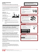
ELECTRICAL CONNECTIONS:
1. Connect 1/2 inch trade size steel conduit to junction box with appropriate fitting. If using Romex-type
shielded wiring, use rectangular pry-out strain reliefs located on upper corners of junction box.
Connect wires accordingly:
• Black (120/277V) or Orange (277V w/ Step Down Transformer) - Supply Voltage
• White - Neutral
• Green / Copper Wire - Grounding Junction Box Wire
0-10V Wiring (/4W or /6WEM):
• Purple - Dim (+)
• Grey - Dim (-)
(Maximum of 8 no. 12 AWG through branch circuit conductors suitable for at least 90°C permitted in
junction box. AC ONLY)
NOTE ON GROUNDING: Many structures carry grounding via steel conduit. If this is the case, if there is no
grounding wire, simply leave green wire on fixture unattached. Fixture will be grounded through attachment
of conduit to junction box. However, if Romex or PVC conduit is used, ground wire will always be present, and
must be connected to green wire on fixture junction box to avoid electrical shock hazard.
WHITE BLUE ORANGE
WHITE (COMMON)
OUTPUT (+)
OUTPUT (-)
INPUT (-)
BLACK (LIVE)
INPUT (+)
WHITE / RED ORANGE YELLOW
TO DRIVER
(INPUT)
TO DRIVER
(OUTPUT)
TO LED LOAD
(INPUT)
LED
EMERGENCY
BATTERY
LED
EMERGENCY
BATTERY
LED
EMERGENCY
BATTERY
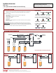
EMERGENCY CONNECTION (NEPK-07LEDUNV)
CONNECTOR 1
CONNECTOR 2
CONNECTOR 3
TO DRIVER
(INPUT)
TO DRIVER
(0-10V)
TO DRIVER
(OUTPUT)
TO LED LOAD
(INPUT)
UNSWITCHED HOT
COMMON
OPTIONAL /6WEM
0-10V DIMMING
WHITE
WHITE (COMMON)
PURPLE (DIM +)
OUTPUT (+)
OUTPUT (-)
BLACK (LIVE)
GREY (DIM -)
BLACK
RED (+)
BLACK (-) BLACK
TEST SWITCH
LED INDICATOR
CONVERTER
CONNECTOR
RED
WHITE / BLUE
WHITE / RED
BLUE
(INPUT) (+)
(INPUT) (-)
ORANGE
YELLOW
SWITCH (OPTIONAL)
FLEX A
FLEX B
CONNECTOR 1
CONNECTOR 4
CONNECTOR 2
CONNECTOR 3
LED
EMERGENCY
BATTERY
WHITE / BLACK
WHITE / BLACK
CONNECTOR 1
CONNECTOR 2
CONNECTOR 3
0-10V DIMMING CONNECTION (/4W OR /6WEM):
Grey - Dim (-)
Purple - Dim (+)
FOR FULL DIAGRAM, REFER TO NEPK-07LEDUNV INSTRUCTIONS