Model No. NETL12915.0 Serial No. Write the serial number in the space above for reference. USER’S MANUAL Serial Number Decal CUSTOMER SERVICE UNITED KINGDOM Call: 0330 123 1045 From Ireland: 053 92 36102 Website: www.iconsupport.eu E-mail: csuk@iconeurope.com Write: ICON Health & Fitness, Ltd. Unit 1D, The Gateway Fryers Way, Silkwood Park OSSETT WF5 9TJ UNITED KINGDOM AUSTRALIA Call: 1800 993 770 E-mail: australiacc@iconfitness.
TABLE OF CONTENTS WARNING DECAL PLACEMENT . . . . . . . . . . . . . . . . . . . . . . . . . . . . . . . . . . . . . . . . . . . . . . . . . . . . . . . . . . . . . . .2 IMPORTANT PRECAUTIONS. . . . . . . . . . . . . . . . . . . . . . . . . . . . . . . . . . . . . . . . . . . . . . . . . . . . . . . . . . . . . . . . . . 3 BEFORE YOU BEGIN. . . . . . . . . . . . . . . . . . . . . . . . . . . . . . . . . . . . . . . . . . . . . . . . . . . . . . . . . . . . . . . . . . . . . . . .5 PART IDENTIFICATION CHART.
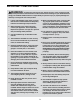
IMPORTANT PRECAUTIONS WARNING: To reduce the risk of burns, fire, electric shock, or injury to persons, read all important precautions and instructions in this manual and all warnings on your treadmill before using your treadmill. ICON assumes no responsibility for personal injury or property damage sustained by or through the use of this product. 1. It is the responsibility of the owner to ensure that all users of this treadmill are adequately informed of all warnings and precautions. 12.
26. Inspect and properly tighten all parts of the treadmill regularly. 22. Never leave the treadmill unattended while it is running. Always remove the key, press the power switch into the off position (see the drawing on page 5 for the location of the power switch), and unplug the power cord when the treadmill is not in use. 27. 23. Do not attempt to move the treadmill until it is properly assembled. (See ASSEMBLY on page 7, and HOW TO FOLD AND MOVE THE TREADMILL on page 28.
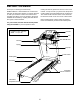
BEFORE YOU BEGIN Thank you for selecting the revolutionary NORDICTRACK® C 320I treadmill. The C 320I treadmill offers an impressive selection of features designed to make your workouts at home more effective and enjoyable. And when you’re not exercising, the unique treadmill can be folded up, requiring less than half the floor space of other treadmills. reading this manual, please see the front cover of this manual.
PART IDENTIFICATION CHART Use the drawings below to identify small parts used for assembly. The number in parentheses below each drawing is the key number of the part, from the PART LIST near the end of this manual. The number following the key number is the quantity used for assembly. Note: If a part is not in the hardware kit, check to see whether it is preattached. Extra parts may be included.
ASSEMBLY • Assembly requires two persons. • To identify small parts, see page 6. • Place all parts in a cleared area and remove the packing materials. Do not dispose of the packing materials until you finish all assembly steps. • Assembly requires the following tools: the included hex key one adjustable wrench • After shipping, there may be an oily substance on the exterior of the treadmill. This is normal.
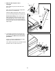
2. Make sure that the power cord is unplugged. 2 Press a Base Cap (74) into each side of the Base (94). Wire 81 Tie 81 Next, remove the tie securing the Upright Wire (81) to the front of the Base (94). 90 Identify the Right Upright (90). Have a second person hold the Right Upright near the Base (94). 74 See the inset drawing. Tie the wire tie in the Right Upright (90) securely around the end of the Upright Wire (81).
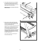
4. Insert a Wheel Spacer (63) into a Front Wheel (62). Hold the Front Wheel inside the bottom of the Right Upright (90), and insert a 3/8" x 4" Screw (7) with a 3/8" Star Washer (13) into the Right Upright and the Front Wheel. 4 Repeat this step on the left side of the treadmill (not shown). 90 13 5. Place a piece of packing material (B) under the right side of the Base (94). Hold the Right Upright (90) against the Base. Make sure not to pinch the Upright Wire (81).
6. Remove and save the four indicated 5/16" x 3/4" Screws (4). 6 4 Identify the Left and Right Base Covers (82, 83). Slide the Left Base Cover onto the Left Upright (89), and slide the Right Base Cover onto the Right Upright (90). Do not press the Base Covers into place yet. 89 82 4 90 83 7. Identify the left handrail assembly (C).
8. Insert the Upright Wire (81) into the bottom of the right handrail assembly (E) and out of the front as shown. 8 28 Attach the right handrail assembly (E) to the Right Upright (90) with two 5/16" x 2 1/2" Screws (28) and two 5/16" Star Washers (11); do not fully tighten the Screws yet. Make sure not to pinch the Upright Wire (81). 11 E 81 D Then, remove and discard the indicated screw (D). 90 9.
10. Set the Console Base (64) face down on a soft surface to avoid scratching the Console Base. If there are ties securing the Pulse Crossbar (93) to the Console Base, remove the ties. 10 2 4 64 18 2 2 Remove and discard the four indicated screws (F). Then, remove the Pulse Crossbar (93). F Remove and save the four 5/16" x 3/4" Screws (4) and the six #8 x 3/4" Screws (2). Then, lift out the two Console Clamps (92) and the Console Frame (18). 92 4 Tie 93 2 Tie 11.
12. IMPORTANT: To avoid damaging the Pulse Crossbar (93), do not use power tools and do not overtighten the #10 x 3/4" Screws (9). 12 9 5 Orient the Pulse Crossbar (93) as shown. Attach the Pulse Crossbar to the Handrails (86) with two #10 x 3/4" Screws (9) and two #10 Star Washers (5); start both Screws, and then tighten them. 28 93 86 9 Make sure not to pinch the Upright Wire (81). Firmly tighten the four 5/16" x 2 1/2" Screws (28). 5 86 28 81 13.
. Set the console assembly on the brackets on the Handrails (86). Make sure not to pinch any wires. 14 Attach the console assembly to the brackets on the Handrails (86) with the four 5/16" x 3/4" Screws (4) that you removed in step 10 and four 5/16" Star Washers (11); do not fully tighten the Screws yet. 86 Insert the excess Upright Wire (81) into the console assembly. Then, pull the two ties tight against the Upright Wire, and cut off the ends of the ties.
16. Carefully slide the Upright Crossbar (41) between the Left and Right Uprights (89, 90). Attach the Upright Crossbar with the four 5/16" x 3/4" Screws (4) that you removed in step 6 and four 5/16" Star Washers (11); start all four Screws, and then tighten them. 16 11 4 41 4 11 89 90 17. Firmly tighten the six 3/8" x 4" Screws (7) (only one side is shown). 17 Then, press the Left Base Cover (82) and the Right Base Cover (83) onto the Base (94).
18. Note: If the treadmill is assembled on a smooth surface, it may roll forward during this step. 18 Raise the Frame (56) to the upright position. Have a second person hold the Frame until step 20 is completed. Brackets Remove the two 5/16" x 3/4" Screws (4) from the Latch Crossbar (38). 11 4 Orient the Latch Crossbar (38) as shown. Make sure that the “This side toward belt” sticker (G) is facing the treadmill.
20. Remove the 5/16" Nut (12) and the 5/16" x 2 1/4" Bolt (3) from the bracket on the Latch Crossbar (38). 20 Align the upper end of the Storage Latch (53) with the bracket on the Latch Crossbar (38), and insert the 5/16" x 2 1/4" Bolt (3) through the bracket and the Storage Latch. This will push a spacer (I) out of the Storage Latch; discard the spacer. 12 I 38 56 Next, tighten the 5/16" Nut (12) onto the 5/16" x 2 1/4" Bolt (3).
SP HOW TO USE THE TREADMILL HOW TO PLUG IN THE POWER CORD Follow the steps below to plug in the power cord. This product must be earthed. If it should malfunction or break down, earthing provides a path of least resistance for electric current to reduce the risk of electric shock. This product’s power cord has an equipment-earthing conductor and an earthing plug. IMPORTANT: If the power cord is damaged, it must be replaced with a manufacturer-recommended power cord. 1.
CONSOLE DIAGRAM FEATURES OF THE CONSOLE You can even listen to your favorite workout music or audio books with the console’s sound system while you exercise. The treadmill console offers an impressive array of features designed to make your workouts more effective and enjoyable. When you use the manual mode, you can change the speed and incline of the treadmill with the touch of a button. As you exercise, the console will display instant exercise feedback.
15 HOW TO TURN ON THE POWER HOW TO USE THE MANUAL MODE IMPORTANT: If the treadmill has been exposed to cold temperatures, allow it to warm to room temperature before you turn on the power. If you do not do this, you may damage the console displays or other electrical components. 1. Insert the key into the console. Plug in the power cord (see page 18). Next, locate the power switch on the treadmill frame near the power cord. Press the power switch into the reset position.
5. Follow your progress with the displays. As you exercise, the workout intensity level bar will indicate the approximate intensity level of your exercise. As you walk or run on the treadmill, the display can show the following workout information: • The elapsed time • The distance that you have walked or run • The workout intensity bar ETNT99212 Press the Home button to return to the default menu (see THE SETTINGS MODE on page 26 to set the default menu).
To measure your heart rate, stand on the foot rails and hold the pulse bar with your palms on the metal contacts; Contacts avoid moving your hands. When your pulse is detected, a heart symbol in the calorie display will flash each time your heart beats, one or two dashes will appear, and then your heart rate will be shown. For the most accurate heart rate reading, continue to hold the contacts for about 15 seconds.
4. Follow your progress with the displays. During the workout, the profiles on the speed and incline tabs Current Segment will show your progress. The flashing segment of the profile represents the current segment of the workout. The height of the flashing segment indicates the speed or incline setting for the current segment. At the end of each segment, a series of tones will sound and the next segment of the profile will begin to flash.
4. Select the duration of the workout. The workout will continue until you reach the goal that you set. The walking belt will then slow to a stop. Use the increase and decrease buttons next to the Enter button to select the desired duration of the workout. Then, press the Enter button. Note: The calorie goal is an estimate of the number of calories that you will burn during the workout. The actual number of calories that you burn will depend on various factors such as your weight. 5.
HOW TO USE AN IFIT WORKOUT To re-run a recent iFit workout from your schedule, first press the Track button. Next, press the increase and decrease buttons to select the desired workout. Then, press the Enter button to start the workout. Note: To use an iFit workout, you must have an optional iFit module. To purchase an iFit module at any time, go to www.iFit.com or call the telephone number on the front cover of this manual.
6. Follow your progress with the displays. THE OPTIONAL CHEST HEART RATE MONITOR See step 5 on page 21. Whether your goal is to burn fat or to strengthen your cardiovascular system, the key to achieving the best results is to maintain the proper heart rate during your workouts. The optional chest heart rate monitor will enable you to continuously monitor your heart rate while you exercise, helping you to reach your personal fitness goals.
2. Select the optional screens. CHECK WIFI STATUS—Press the Enter button to check the status of your iFit module. The lower display will show the software version number, the network SSID, the network encryption type, the connection status, the wireless signal strength, the IP address of the module, the number of registered users and their names, the results of the DNS lookup, and the status of the iFit server. While the settings mode is selected, the matrix will display several optional screens.
HOW TO FOLD AND MOVE THE TREADMILL HOW TO FOLD THE TREADMILL HOW TO MOVE THE TREADMILL To avoid damaging the treadmill, adjust the incline to zero before you fold the treadmill. Then, remove the key and unplug the power cord. CAUTION: You must be able to safely lift 45 lbs. (20 kg) to raise, lower, or move the treadmill. Before moving the treadmill, fold it as described at the left. CAUTION: Make sure that the storage latch is locked in the storage position. Moving the treadmill may require two people.
MAINTENANCE AND TROUBLESHOOTING MAINTENANCE SYMPTOM: The power turns off during use Regularly clean the treadmill and keep the walking belt clean and dry. First, press the power switch into the off position and unplug the power cord. Wipe exterior parts of the treadmill with a damp cloth and a small amount of mild soap. IMPORTANT: Do not spray liquids directly onto the treadmill. To avoid damage to the console, keep liquids away from the console. Then, thoroughly dry the treadmill with a soft towel. a.
SYMPTOM: The walking belt slows when walked on Locate the Reed Switch (52) and the Magnet (50) on the left side of the Pulley (49). Turn the Pulley until the Magnet is aligned with the Reed Switch. Make sure that the gap between the Magnet and the Reed Switch is about 1/8 in. (3 mm). If necessary, loosen the #8 x 3/4" Truss Head Screw (14), move the Reed Switch slightly, and then retighten the Truss Head Screw.
SYMPTOM: The walking belt is not centered between the foot rails. IMPORTANT: If the walking belt rubs against the foot rails, the walking belt may become damaged. SYMPTOM: The walking belt slips when walked on a. F irst, remove the key and UNPLUG THE POWER CORD. Using the hex key, turn both idler roller screws clockwise, 1/4 of a turn. When the walking belt is correctly tightened, you should be able to lift each edge of the walking belt 2 to 3 in. (5 to 7 cm) off the walking platform.
EXERCISE GUIDELINES Burning Fat—To burn fat effectively, you must exercise at a low intensity level for a sustained period of time. During the first few minutes of exercise, your body uses carbohydrate calories for energy. Only after the first few minutes of exercise does your body begin to use stored fat calories for energy. If your goal is to burn fat, adjust the intensity of your exercise until your heart rate is near the lowest number in your training zone.
SUGGESTED STRETCHES The correct form for several basic stretches is shown at the right. Move slowly as you stretch—never bounce. 1. Toe Touch Stretch Stand with your knees bent slightly and slowly bend forward from your hips. Allow your back and shoulders to relax as you reach down toward your toes as far as possible. Hold for 15 counts, then relax. Repeat 3 times. Stretches: Hamstrings, back of knees and back. 1 2. Hamstring Stretch Sit with one leg extended.
PART LIST Key No. Qty. 1 2 3 4 5 6 7 8 9 10 11 12 13 14 15 16 17 18 19 20 21 22 23 24 25 26 27 28 29 30 31 32 33 34 35 36 37 38 39 40 41 42 43 44 45 46 47 48 18 37 1 10 2 1 6 1 2 9 14 2 6 19 3 1 2 1 4 2 2 2 4 2 2 2 1 4 1 4 2 2 6 4 13 1 8 1 6 2 1 1 1 1 1 2 1 4 Model No. NETL12915.0 R0115A Description Key No. Qty.
Key No. Qty. 97 98 99 2 1 1 Description Key No. Qty. Motor Isolator Electronics Bracket Filter 100 101 * 1 1 – Description Motor Isolator Receptacle User’s Manual Note: Specifications are subject to change without notice. For information about ordering replacement parts, see the back cover of this manual. *These parts are not illustrated.
15 35 1 36 2 59 30 34 23 84 39 40 2 61 37 43 35 1 2 57 44 15 35 39 35 11 4 1 2 40 39 35 23 2 45 84 37 42 47 35 35 60 19 84 56 39 37 59 30 34 46 30 84 35 1 37 34 59 37 12 84 11 4 35 49 3 1 35 23 14 50 51 31 21 10 37 84 53 39 52 55 35 37 39 35 1 35 97 19 20 84 59 30 34 15 54 38 12 46 23 48 10 10 31 6 21 100 10 10 99 73 98 10 24 EXPLODED DRAWING A Model No. NETL12915.
EXPLODED DRAWING B Model No. NETL12915.
EXPLODED DRAWING C Model No. NETL12915.
EXPLODED DRAWING D Model No. NETL12915.
ORDERING REPLACEMENT PARTS To order replacement parts, please see the front cover of this manual.