
Operation Manual

9
4
3
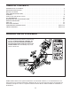
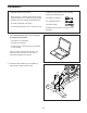
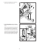
3. Attach the Front Stabilizer (3) to the Base (2)
with two M10 x 20mm Screws (105).
3
2
105
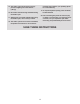
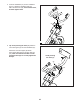
4. See the inset drawing. Orient the Handlebar
Post (7) so that the lower slot (A) is on the side
shown.
Next, loosen the indicated Post Knob (100) and
insert the Handlebar Post (7) into the Frame
(1) until the lower end of the Handlebar Post is
below the Frame. Then, tighten the Post Knob.
Then, insert the end of the Lower Wire (122) into
the Frame (1) and the Handlebar Post (7) and
pull it out of the upper slot (B) in the Handlebar
Post as shown by the dashed line at the right.
100
100
122
7
A
B
1
7
1