
Datasheet


9/08
®
®
N/en 5.3.541.06
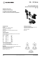
V50 ... V53 Series
Our policy is one of continued research and development. We therefore reserve the right to amend,
without notice, the specifications given in this document.
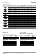
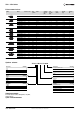
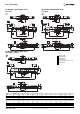
Valve dimensions
4
3
2
1
Manual override
(Push and Turn)
Gland size Pg 7
Solenoid rotates
2 x 180° (V50), 4 x 90° (V51 ... V53)
Gland size Pg 9
NAD
R
A
PR
Q
CAB
D
P
M
B
V
A
S
T
U
W
H
G
X
F
E
2
3
1
J
LAC
NAD
R
A
PR
Q
CAB
D
P
J
M
LAC
V
S
T
U
HI
G
F
E
A
1
4
3
B
W
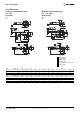
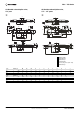
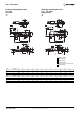
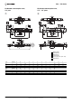
Serie Drawing A AB AC AD B C D E F G H I J
V50 1 99,5 13,5 21,5 15,5 65 15 3,2 55,5 27 5 3 - 1/8“
V51 2 106,5 13,5 17 13,5 69 25 4,2 67 35 8,5 3 3 1/4“
V52 2 126,5 13 26 15 89 26 4,5 73 46,5 39,5 4 3 3/8“
V53 2 133 12,5 27 15 96 29 4,5 73 46,5 39,5 4 3 1/2“
Serie Drawing L M N P Q R S T U V W X
V50 1 14,5 108 23 1/8“ 3,2 6 1 13 18 29,5 16 0,5
V51 2 18 120 25 1/4“ 3,2 6 2 17 22,5 26 22 -
V52 2 26 139,5 41 3/8“ 4,5 8 - 23 30 41 22 -
V53 2 29 146 48 1/2“ 4,2 8 2,5 23 30 40,5 22 -
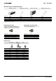
3/2 Single solenoid pilot valve,
1/4”... 1/2” ports
Spring return
3/2 Single solenoid pilot valve,
1/8” port
Air return