
Datasheet


11/08
®
®
N/de 5.3.541.10
Serie V50 ... V53
Konstruktionsänderungen vorbehalten
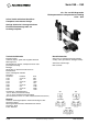
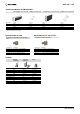
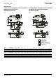
5/3 Bistabiles elektropneumatisch betätigtes
Wegeventil, Anschluss G1/4
5/3 Bistabiles elektropneumatisch betätigtes
Wegeventil, Anschluss G1/8
11
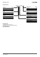
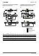
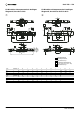
5/3 Bistabiles elektropneumatisch betätigtes
Wegeventil, Anschlüsse G3/8 und G1/2
BA
PR2 R1
C
D
V
J
L
K
B
A
H
G
F
E
2
N
R
O
Q
P
M
S
T
U
1
W
3
N
Q
P
J
R
O
C
P
AB
R2 R1
D
K
B
A
M
S
T
U
L
V
G
H
I
F
E
1
4
3
W
N
Q
P
J
R
O
C
P
AB
R2 R1
D
K
B
A
M
S
T
U
L
G
H
I
F
E
1
4
3
W
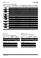
Serie Zeichnung A B C D E F G H I J K L
V50 9 164 96 14,5 3,2 55 27 5 3 - G1/8 G1/8 29
V51 10 194 119 20 4,2 67 35 7 3 3 G1/4 G1/8 36
V52 11 254,5 179,5 26 5,5 73 46,5 4,5 4 3 G3/8 G3/8 52
V53 11 265,5 191,5 29 4,5 73 46,5 7 4 3 G1/2 G1/2 58
Serie Zeichnung M N O P Q R S T U V W
V50 9 181 34 16 G1/8 3,2 6 2 13 18 43,5 16
V51 10 221 38 21 G1/4 3,2 6 3 17 22,5 48,5 22
V52 11 281,5 13 30 G3/8 4,5 8 - 23 30 - 22
V53 11 291,5 72 28 G1/2 4,2 8 4,5 23 30 - 22
4
3
2
1
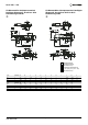
Handhilfsbetätigung
Druckknopf arretierbar
Kabelanschluss Pg 7
Drehwinkel des Elektomagneten
2 x 180° (V50), 4 x 90° (V51 ... V53)
Kabelanschluss Pg 9