Standard 1.1 Part No.
Standard 1.1 2 Copyright © 2001-2005 Nortel All rights reserved. The information in this document is subject to change without notice. The statements, configurations, technical data, and recommendations in this document are believed to be accurate and reliable, but are presented without express or implied warranty. Users must take full responsibility for their applications of any product specified in this document. Printed in Canada. Trademarks NORTEL© is a registered trademark of Nortel.
Standard 1.1 3 Preface Congratulations on your purchase of the Remote Gateway 911x series unit. With the Remote Gateway 911x product you have the advantage of a full featured host PBX at your home office. This Quick Start Guide gets you up and running with your Remote Gateway unit.
Standard 1.
Standard 1.1 5 Installation You need a 10BaseT Ethernet cable to provide the Remote Gateway 911x series unit with voice over IP capability. For instructions on how to install a Remote Gateway 911x unit turn to “Installing the Remote Gateway 911x unit” on page 7.
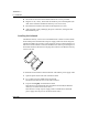
Standard 1.1 6 Installation 5 Secure the circuit card to the footstand with the two screws provided. 6 Plug the 18 cm (7 inch), TCM cable into the RJ11 jack on the telephone (the other end is attached to the Remote Gateway 9110 circuit card). 7 Re-attach the footstand to the bottom of the telephone (2 screws). 8 Apply the label overlay identifying the power connection, analog line and RJ-45 Ethernet jack.
Standard 1.1 Installation 7 4 Close and latch the ferrite bead. Note: You may need to adjust the cable loops to make them as tight as possible. Installing the Remote Gateway 911x unit To install the Remote Gateway 911x unit on a desk, attach the rubber feet to the bottom and continue with “Connecting the Remote Gateway 911x series unit to the network” on page 7.
Standard 1.1 8 Installation To connect the Remote Gateway 911x series unit to the power source as follows: 1 Connect the plug on the power transformer to the POWER connector on the Remote Gateway 911x series unit. 2 Attach the power cord to the power transformer. 3 Plug the power supply into an uninterruptible power source (UPS) or wall outlet. As soon as you connect the Remote Gateway 911x unit to the power source, the unit begins to power up and the power LED comes on.
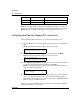
Standard 1.1 9 Configuration You can configure the Remote Gateway 911x series unit through the telephone set. The procedure is the same for either the Remote Gateway 9110 circuit card or 9115 unit. Before you begin, your System Administrator must supply you with a completed Remote Gateway 911x series telephone menu — Configuration Values form. Use the information provided on this form to configure the Remote Gateway 911x series unit.
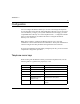
Standard 1.1 10 Configuration Key name Key label 911x telephone menu key function ASTERISK * period (.), delimiter for IP addresses POUND # backspace with delete Note: If, at any time while working with the telephone set menu, you make a mistake, you can return to the previous level in the menu system by pressing the Release (Rls, R, or Goodbye depending on your telephone set) key once.