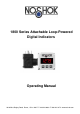
800 Series Attachable Loop-Powered Digital Indicators Operating Manual 1010 West Bagley Road, Berea, Ohio 44017 P 440.243.0888 F 440.243.3472 www.noshok.
Index 1 INTRODUCTION 2 SAFETY REGULATIONS 3 ELECTRIC CONNECTION 3.1 ADJUSTMENT OF THE CONNECTIONS: 3.2 CONNECTION EXAMPLE: 3.2.1 Switching of a relay 3.2.2 Switching of a relay 4 CONFIGURATION: DISPLAY ADJUSTMENT TO THE TRANSMITTER 4.1 CONFIGURATION OF THE INPUT SIGNAL 4.2 SELECTION OF THE OUTPUT FUNCTION 5 SWITCHING POINTS RESP. ALARM-BOUNDARIES: 5.1 2-POINT-CONTROLLER 5.
1 Introduction The indicator with LED-display is a microprocessor controlled displaying, monitoring and controlling device. In according to his type the device is supporting an input for: - standard signal 4 – 20 mA - standard signal 0 – 10 V The device features one switching output (npn-output), which can be configured as 2-pointcontroller or min./max. alarm output. The state of the switching output is displayed with the LED left beneath the LED-display.
Attention: When running electric devices, parts of them will always be electrically live. Unless the warnings are observed serious personal injuries or damage to property may result. Skilled personnel only should be allowed to work with this device. For trouble-free and safe operation of the device please ensure professional transport, storage, installation and connection as well as proper operation and maintenance.
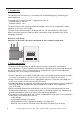
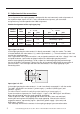
3.1 Adjustment of the connections The assignment of the angle-type plug is designed for the most commonly used assignments of the respective input signals. As this is not a standardised assignment, your transmitter assignment may not correspond to the 1800 assignment. Standard assignment of the angle-type plug: contact number wire color 1 2 blue red 3 black 4( ) 4 … 20 mA pin jack display.. + display.. fed through switching n.c. output + switching n.c.
General instruction for change of the angle-type plug assignment: Remove the coupling insert by means of a screw driver at the position indicated (arrow). Change the assignment according the notes of the respective input signal. Latch coupling insert in cover. You have a choice between 4 different orientations – each of them spaced 90°. Put on angel-type plug and connect plugs using the long screw delivered (do not forget seals). 3.
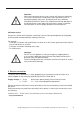
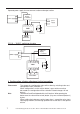
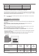
Separate power supply for measurement section and output section power supply additional display o. controller + + 1 2 3 power power supplyl supply 4 GRA 0420 VO 1800 1 2 + - 3 4 transmitter 3.2.2 0 … 10 VDC: switching of a relay power supply additionl additional display display o. controller controller o. + 1 2 3 4 1999.200 1800 1 + 2 3 - 4 Sig.
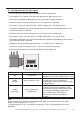
4.1 Configuration of the input signal - Turn the device on and wait until it completed its built-in segment test. - Press button 2 for 1 second, in the device display appears ‚ dP’ (decimal point). - Select the desired decimal point place by pressing button 2 respective button 3. - Validate the selected value by pressing button 1. The display shows ‚ dP’ again. - Press button 1 again, the display will show “ di.Lo“ (Di splay Low = low display value).
- Press button 1 to validate the selection, the display shows “ Li“ again. - When pressing button 1 again, the display will show “ FiLt“ (Filter). - Use button 2 and button 3 to select the desired filter behavior 0 = filter deactivated 1 = filter stage 1: suppresses jumping display values caused be smallest changes 2 = filter stage 2: additional suppression of measuring peaks (causes delayed reaction of switching output) - Press button 1 to validate your value, the display shows “ FiLt“ again.
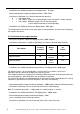
Display Preferred state of the output off Inactive in case of an error on Active in case of an error Note - Press button 1 to validate the selection. The display shows “ 1.Err“ again. The configuration of the output function is now completed. Depending on the selected output function you have to make the settings for switching / alarm points. See description in chapter “Switching points / alarm-boundaries“ for further information.
5.1 2-point-controller This chapter describes how to configure the switching points as use the device for a 2-pointcontroller. This instruction demands that you selected“ 2P“ as your desired output function. - Press button 1 (when not already done). The device will display “ 1.on“ (turn-on-point). - Use button 2 and button 3 to set the desired value, the device’s output should be turning on. - Press button 1 to validate your selection. The display shows “ 1.on“ again.
- Press button 1 to validate the delay time. The display shows “ A.dEL“ again. Example: You want to have a temperature alarm-monitoring of a greenhouse. The alarm should start when the temperature rises above 50°C or falls below 15°C. Therefore your settings will be 50°C for the maximum alarm-value “AL.HI“ and 15°C for the minimum alarm-value “AL.Lo“.
- Press button 1 to validate your selection. The display shows “OFFS“ again. - When pressing button 1 again, the device will display “SCAL“ (scale = slope). - Use button 2 and button 3 to select the desired slope-adjustment. The slope adjustment will be entered in %. The value displayed can be calculated like this: Display = (measured value – offset – di.Lo) * (1 + slope adjustment [% / 100] ) + di.Lo Example: The setting is 2.00 => the slope has risen 2.00% => slope = 102%.
8 Error codes When detecting an operating state which is not permissible, the device will display an error code. The following error codes are defined: Err.1: Exceeding of the measuring range Indicates that the valid measuring range of the device has been exceeded. Possible causes: - Input signal to high - Sensor shorted (0(4)-20mA) Remedies: - The error-message will be reset if the input signal is within the limits. - check transmitter and device configuration (e.g. input signal). Err.
9 Specification Signal: Voltage load: Input resistance: Max. permissible input: Supply voltage: Supply current: Display: Display range: max. display value: min.
CORPORATE HEADQUARTERS 1010 West Bagley Road · Berea, Ohio 44017 Ph 440-243-0888 · Fax 440.243.3472 E-mail: noshok@noshok.com Web: www.noshok.