Novation A division of Focusrite Audio Engineering Ltd. Windsor House Turnpike Road Cressex Business Park High Wycombe Buckinghamshire HP12 3FX United Kingdom Tel: +44 1494 462246 Fax: +44 1494 459920 e-mail: sales@novationmusic.com Web: http://www.novationmusic.com Trade marks The Novation trade mark is owned by Focusrite Audio Engineering Ltd. All other brand,product and company names and any other registered names or trade marks mentioned in this manual belong to their respective owners.
CONTENTS COPYRIGHT AND LEGAL NOTICES . . . . . . . . . . . . . . . . . . . . . . . . . . . . . . . . . . . . . . . . . . . 2 INTRODUCTION . . . . . . . . . . . . . . . . . . . . . . . . . . . . . . . . . . . . . . . . . . . . . . . . . . . . . . . . . . . . . 4 Key Features . . . . . . . . . . . . . . . . . . . . . . . . . . . . . . . . . . . . . . . . . . . . . . . . . . . . . . . . . . . . . 4 About This Manual . . . . . . . . . . . . . . . . . . . . . . . . . . . . . . . . . . . . . . . . . . . . . .
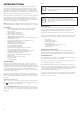
INTRODUCTION Tips These do what it says on the tin: we include bits of advice, relevant to the topic being discussed that should simplify setting up Peak to do what you want. It’s not mandatory that you follow them, but generally they should make life easier. Thank you for purchasing this Peak eight voice polyphonic desktop synthesiser, the best sounding synth Novation has ever made.
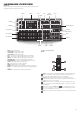
HARDWARE OVERVIEW Top Panel Peak’s control surface is divided logically into functional areas, with signal generation and treatment broadly following a left-to-right sequence.
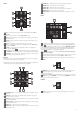
OSCILLATORS: 7 MIXER: 8 9 10 11 12 14 13 The three Oscillators have identical sets of controls. All have further parameters available for adjustment via the menu system; these are described in detail later in the User Guide. 7 Range – steps through the oscillator’s base pitch ranges. For standard concert pitch (A3 = 440 Hz), set to 8’. 8 Coarse – adjusts the pitch of the selected oscillator over a range of ±1 octave. 9 Fine – adjusts the oscillator pitch over a range of ±100 cents (±1 semitone).
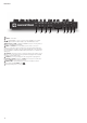
FILTER: 49 REVERB: Type – emulates spaces of three different sizes: 3 is the largest. 50 REVERB: Level – controls the “amount” of reverberation. 41 51 CHORUS: Rate – adjusts the rate of chorus modulation. 52 CHORUS: Type – lets you select one of three different chorus algorithms. 53 CHORUS: Level – controls the degree of chorus effect. 40 42 39 37 38 36 34 33 54 EFFECTS: Bypass – the three time-domain effects may be switched in or out with this button.
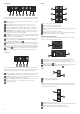
Rear Panel 8 7 1 +12V DC – connect the supplied PSU here. 2 POWER – on/off switch. 3 – standard USB 2.0 or 3.0 port. Connect to a Type A USB port on a computer using the supplied cable. Note that the USB port only carries MIDI data, not audio. 4 MIDI IN, OUT and THRU – standard 5-pin DIN MIDI sockets for connecting Peak to a keyboard or other MIDI-equipped hardware. 5 PEDAL 1 and PEDAL 2 – two 3-pole (TRS) ¼” jack sockets for connection of switch (e.g., sustain) and/or expression pedals.
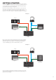
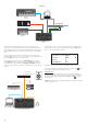
GETTING STARTED Peak may, of course, be used simply as a standalone synthesiser with a master keyboard connected to its MIDI IN socket. However, there are many more possibilities, and how you choose to integrate it into your existing synth/recording setup will be determined by the other equipment you have and your own imagination! Below are three examples illustrating how Peak could form part of a synth setup.
Example 3 Computer USB Euroack Novation Launchkey USB THUNDERBOLT USB LFO OUT Focusrite Clarett Eurorack AUDIO I/O MIDI OUT USB MIDI IN CV IN MIDI THRU MIDI IN MIDI OUT MIDI IN Novation Bass Station II Novation Peak In this example, a Focusrite Clarett audio interface is used to enable “real-world” instruments to be recorded in the DAW as well as synth sounds.
Menu Navigation Saving Patches Although most of the key parameters affecting the nature of the sound Peak generates are immediately accessible through dedicated, “per-function” rotary controls and switches, many further parameters and synth settings can be modified using the OLED display and its associated controls. Patches can be saved to any of the 512 memory locations, but remember that if you save your settings to any location in Banks A or B, you will overwrite one of the factory presets.
Basic Operation – sound modification MIDI control Once you have loaded a Patch you like the sound of, you can modify the sound in many different ways using the synth controls. Each area of the control panel is dealt with in greater depth later in the manual, but a few fundamental points should be noted first.
SYNTHESIS TUTORIAL This section covers the general principles of electronic sound generation and processing in more detail, including references to Peak’s facilities where relevant. It is recommended that this chapter is read carefully if analogue sound synthesis is an unfamiliar subject. Users familiar with this subject can skip this section and move on to the next.
Volume 1 harmonic content present in each of the two oscillator signals, and will consist of a series of sum and difference frequencies as well as the frequencies present in the original signals. Harmonic Sine Wave Sawtooth Waves Volume OSC 1 1 Sawtooth Wave 2 3 4 X 5 Harmonic OSC 2 Volume These are rich in harmonics, and contain both even and odd harmonics of the fundamental frequency. The volume of each is inversely proportional to its position in the harmonic Volume series.
Frequency being produced is actually a pure sine wave, the pitch of which depends on the setting of the Frequency control (the filter’s cut-off point). This resonance-produced sine wave can actually be used for some sounds as an additional sound source if wished. Cut-off Frequency Cut-off Frequency Volume The diagram below shows the response of a typical low-pass filter. Frequencies above the cut-off point are reduced in volume.
TIME A waveshape often used for an LFO is a Triangle wave. KEY "ON" KEY "OFF" PITCH VOLUME PITCH WITHOUT MODULATION SUSTAIN ATTACK DECAY RELEASE TIME TIME Attack Time Adjusts the time it takes after a key is pressed for the volume to climb from zero to full volume. It can be used to create a sound with a slow fade-in. KEY "ON" KEY "OFF" Decay Time Adjusts the time it takes for the volume to fall from its initial full volume to the level set by the Sustain control while a key is held down.
PEAK: SIMPLIFIED BLOCK DIAGRAM FPGA Analogue Voice 1 Osc1 Osc2 Osc3 Voice 2 Voice 3 Mixer Mixer Mixer Overdrive Overdrive Overdrive Analogue Analogue Filter Pre VCA Distortion VCA left Analogue Filter Pre VCA Distortion VCA left Filter Pre VCA Distortion VCA left VCA right VCA right VCA right Voice 4 Mixer Overdrive Filter Pre VCA Distortion VCA left Voice 5 Mixer Overdrive Filter Pre VCA Distortion VCA left Filter Pre VCA Distortion VCA left Filter Pre VCA Distorti
Pitch The Oscillator Menu The three controls Range 7 , Coarse 8 and Fine 9 set the Oscillator’s fundamental frequency (or Pitch). The Range button selects traditional “organ-stop” units, where 16’ gives the lowest frequency and 2’ the highest. Each doubling of stop length halves the frequency and thus transposes the pitch of a note played at the same position on a keyboard down one octave. When Range is set to 8’, the keyboard will be at concert pitch with Middle C in the centre.
Oscillator Sync Displayed as: Initial value: Range of adjustment: VSync 0 0 to 127 Oscillator Sync is traditionally a technique of using one oscillator (the master) to add harmonics to another (the slave). Peak provides Oscillator Sync by using a virtual oscillator for each of the three main oscillators. The virtual oscillators are not heard, but the frequency of each is used to re-trigger that of the main oscillator.
The LFO Section The LFO Menu Each of Peak’s LFOs are ‘per voice’. This is a very powerful feature of Peak (and other Novation synthesisers). For example, when an LFO is assigned to create vibrato, and a chord is played, each note of the chord will be varied at the same rate, but not necessarily at the same phase. There are various settings in the LFO Menu that control how the LFOs respond and lock together. Each LFO has two menu pages; the parameters available for each LFO are identical.
LFO Slew Displayed as: Initial value: Range of adjustment: Slew 0 0 to 127 Slew has the effect of modifying the shape of the LFO waveform. Sharp edges become less sharp as Slew is increased. The effect of this can be heard on pitch modulation by selecting Square as the LFO waveform and setting the rate fairly low so that when a key is pressed the output alternates between just two tones.
The Mixer Section The Envelopes Section 19 Peak generates three envelopes each time a key is pressed, which can be used to modify the synth sound in many ways. The envelope controls are based on the familiar ADSR concept. 24 KEY "ON" 20 22 21 23 KEY "OFF" VOLUME SUSTAIN ATTACK DECAY RELEASE TIME MIXER TO ENVELOPES SECTION The ADSR envelope can be most easily visualised by considering the amplitude (volume) of a note over time.
Multi-Triggering Displayed as: Initial value: Range of adjustment: 25 26 27 • • • When this parameter is set to Re-Trig, each note played will trigger its full ADSR envelope, even if other keys are held down. In Legato mode, only the first key to be pressed will produce a note with the full envelope, all subsequent notes will omit the attack and decay phases, and sound only from the start of the Sustain phase. “Legato” literally means “smoothly”, and this mode aids this style of playing.
The Filter Section Frequency The large rotary Frequency control 35 sets the cut-off frequency of the filter when Shape is set to HP or LP. With BP selected, Frequency sets the centre frequency of the filter’s pass-band. 41 Sweeping the filter frequency manually will impose a “hard-to-soft” characteristic on almost any sound. 42 40 Resonance 39 37 38 36 34 33 The Resonance control 36 adds gain to the signal in a narrow band of frequencies around the frequency set by the Frequency control.
Filter tracking The pitch of the note played can be made to alter the cut-off frequency of the filter. This relationship is governed by the setting of the Key Tracking control 42 . At the maximum value (127), the filter cut-off frequency moves in semitone steps with the notes played on the keyboard – i.e., the filter tracks the pitch changes in a 1:1 ratio. This means that when playing two notes an octave apart, the filter cut off frequency will also change by one octave.
The Modulation Matrix The heart of a versatile synthesiser lies in the ability to interconnect the various controllers, sound generators and processing blocks such that one block is controlling – or “modulating” - another, in as many ways as possible. Peak provides considerable flexibility of control routing, and there is a dedicated menu for this, the Mod Menu.
You need to be careful when setting up matrix assignments like this to ensure that the combined effect of all the controllers acting simultaneously still creates the sound that you want. In addition, the Modulation Menu lets you assign the two ANIMATE buttons as sources (see page 12). Slot number Displayed as: Initial value: Range of adjustment: Slot 1 1 to 16 Slot lets you select one of 16 ‘slots’, each defining a routing assignment of one (or two) sources to a destination.
Press the Voice button 56 to open the Voice Menu, which comprises three pages. In addition to selecting polyphonic or mono voicing, the menu also lets you set how Glide operates and other related voicing parameters.
Polyphony Mode Displayed as: Initial value: Range of adjustment: The Arpeggiator Mode Poly Mono, MonoLG, Mono2, Poly, Poly2 As the names imply, three of the possible modes are mono and two are polyphonic. 1. 2. 3. 4. 5. Peak has a versatile Arpeggiator (Arp) feature which allows arpeggios of varying complexity and rhythm to be played and manipulated in real-time. When the Arpeggiator is enabled and a single key is pressed, its note will be retriggered.
Tempo Displayed as: Initial value: Range of adjustment: ClockRate 120 BPM 40 to 240 BPM ClockRate sets the basic tempo of the arp sequence and you can make it play faster or slower by adjusting it. The range is 40 to 240 BPM. If Peak is being synchronised to an external MIDI clock, it will automatically detect the incoming tempo and disable the internal clock. The tempo of the arp sequence will then be determined by the external MIDI clock.
The Effects Section Peak comes equipped with a sound effects (FX) section. FX can be applied to the sound the synth is generating to add colour and character. All FX parameters are saved with the Patch. 51 52 The output of the delay processor is connected back to the input, at a reduced level; The Feedback control 46 sets the level. This results in multiple echoes, as the delayed signal is further repeated. With Feedback set to zero, no delayed signal at all is fed back, so only a single echo results.
Chorus EQ Displayed as: Initial values: Range of adjustment: Width LoPass 90 and 0 to 127 Displayed as: Initial value: Range of adjustment: HiPass 2 0 to 127 The LoPass and HiPass parameters adjust simple HF and LF filters within the Chorus processor. Adjusting these will enhance or mask some of the additional harmonics added to the sound by the Chorus effect.
Reverb EQ Displayed as: Initial values: Range of adjustment: The Settings Menu LoPass 74 and 0 to 127 HiPass 0 0 to 127 Press the Settings button 56 opens the Settings Menu (eight pages). This menu contains a set of synth and system functions which, once set up, will not generally need to be accessed on a regular basis. The Settings Menu includes Patch backup routines, MIDI and pedal settings among other functions.
Message Time Displayed as: Initial value: Range of adjustment: Transpose Displayed as: Default value: Range of adjustment: Msg Time 64 0 to 127 Msg Time sets the time for which parameter values (and the saved value for the current Patch) are displayed when a rotary control is adjusted. The maximum time (value = 127) is equivalent to approx. 3 seconds.
Patch Select Displayed as: Default value: Range of adjustment: Bank/Patch Rec+Tran Disabled, Receive, Transmit, Rec+Tran This setting controls how Peak handles MIDI Program Change and Bank Change messages. The default value of Rec+Trans allows Peak to send a Program/Bank Change message whenever a new Patch is loaded, and also lets you load a Patch from an external MIDI controller, such as Novation Impulse.
APPENDIX LFO Sync Rate This table lists the sync rate divisions available for the LFO Sync clock; these are displayed when an LFO Rate control 18 is adjusted with Range 17 set to Sync. System Updates using Novation Components Novation Components is an online Patch Librarian, which allows you to manage your Patch library. You can also restore original factory Patches and download new ones as they become available.
Init Patch – parameter table This list gives the values of all synth parameters in the Init Patch (the factory Patch initially loaded into Banks C and D). Parameters in italics are those accessed via the menu system.
Modulation Matrix – sources The table below lists the sources of modulation available to Inputs A and B of each Slot in the Modulation Matrix. MIDI parameters list Parameter CC/ NRPN Control Number.
Parameter CC/ NRPN Control Number. Range Default Value Parameter CC/ NRPN Control Number.
Range Default Value 104 0-127 (0 to +127) 0 (0) NRPN 0:88 0-1 (0 to +1) 0 (0) Effects Routing NRPN 0:89 0-6 (0 to +6) 0 (0) Delay Level CC 108 0-127 (0 to +127) 0 (0) Delay Time CC 109 0-127 (0 to +127) 0 (64) Delay Width NRPN 0:92 0-127 (0 to +127) 0 (64) Parameter CC/ NRPN Distortion Level CC Effects Master Bypass Control Number. Effects Parameter CC/ NRPN Control Number.
Parameter CC/ NRPN Control Number.