
User Manual


8
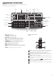
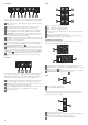
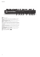
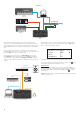
Rear Panel
1
+12V DC – connect the supplied PSU here.
2
POWER – on/off switch.
3
– standard USB 2.0 or 3.0 port. Connect to a Type A USB port on a computer
using the supplied cable. Note that the USB port only carries MIDI data, not audio.
4
MIDI IN, OUT and THRU – standard 5-pin DIN MIDI sockets for connecting Peak to a
keyboard or other MIDI-equipped hardware.
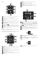
5
PEDAL 1 and PEDAL 2 – two 3-pole (TRS) ¼” jack sockets for connection of
switch (e.g., sustain) and/or expression pedals. The sockets detect switch pedal polarity
automatically. Expression pedals are also detected automatically and can be routed directly
as sources available to the Modulation Matrix. Switch pedal functions are configured in the
Settings menu.
6
CV MOD IN – 3.5 mm jack socket for connecting an external Control Voltage source in
the range of +/-5 V. This permits other analogue instruments (equipped with a compatible
CV output) to modulate Peak’s sounds.
7
OUTPUTS – two ¼” 3-pole (TRS) jack sockets carrying Peak’s output signal. Use
both L/MONO and RIGHT for full stereo: if RIGHT is unconnected, a mono (L+R) sum is
available at L/MONO. Outputs are pseudo-balanced.
8
HEADPHONES – 3-pole (TRS) ¼” jack socket for stereo headphones. Phones
volume is adjusted by the VOLUME control
61
.
9
Kensington Security Slot – to secure your synth.
8
7
6
5
4
3
1 2 9