
Installation Sheet


STEP 1: Remove diffuser from housing : Near one end of
housing, grasp edge of diffuser and carefully squeeze to release
diffuser from housing. Continue down length of diffuser to fully
disengage.
STEP 2: Remove xture components and parts pack(s). Check that
all parts are included.
STEP 3: To remove knockouts: Place standard screwdriver on
center of slot and gently strike with hammer. Grip edge with pliers
and ex back and forth until removed. Romex or other connector
not supplied.
STEP 4: With the power turned off, thread two Screws
into
junction box (Note: screws must be the same distance apart as
keyholes in back of housing assembly).
STEP 5: Hold the Fixture Housing
rmly and connect the green
ground wire from the xture to the bare copper ground wire from the
junction box using a Wire nut
. (If house wiring does not include
a ground wire, consult your local electrical code for approved
grounding methods).
STEP 6: Use Wire nuts
to connect the black xture wire to the
black power supply wire and the white (neutral) xture wire to the
white power supply wire (See Figure 1).
STEP 7: Hold Fixture Housing
in one hand and with the other
hand position wires up into junction box.
STEP 8: Align keyholes on back of Fixture Housing with screws
previously installed in junction box. Lift xture up, rotate clockwise
and tighten screws to secure Housing Assembly against ceiling.
STEP 9: To install diffuser
: Starting at one end of housing, insert
diffuser slot onto edge of housing (See Figure 2). Carefully squeeze
diffuser to engage opposite side with housing. Continue this action
down length of diffuser until fully installed onto housing.
STEP 10: Turn on electricity at fuse or circuit breaker box and verify
success of installation.
CAUTION: Read the instruction carefully and save them. Failure to install and wire
xture or Install In accordance with the National Electrical Codes (NEC), all applicable
Federal, State and Local electrical codes, as well as specic U.L. safety standards for
the intended working environment (location/application), may cause serious personal
injury, death and/or property damage. This product must be installed by a person
familiar with the construction and operation of the product and the hazards involved.
SAFETY INFORMATION
100~277V 50/60Hz. FOR INDOOR OR DAMP LOCATION.
WARNING: LED module are integrated to the xture and are not removable or
replaceable. Ensure the electricity to the wires you are working on is shut off. Either
remove the fuse or turn off the circuit breaker. Only the electrician or electrical engineer
who has the qualied certication can be allowed to install this product.
LED Wrap Fixture
Models: 65-1081, 60-1082, 60-1083, 60-1084, 65-1091,
65-1092, 65-1095, 65-1096, 65-1097, 65-1098
Satco Products, Inc.
Bre ntwood, N Y 11717
INSTALLATION
External Wiring Method*
INSTALLATION AND SAFETY INSTRUCTIONS
IMPORTANT: Read before installing xture. Retain for future reference.
* See back for Internal Wiring Method
© Copyright 2017 Satco Products, Inc. 3/17
ASSEMBLY PART LIST
Figure 2
Part Description Quantity
Screw 2
Fixture Housing 1
Wire nuts 3
Diffuser 1
Wire Compartment Cover 1
Wire Compartment Cover Screw
1
Reector 1
Drywall Anchor 2
Wood Screw 2
Specications Model WRA-20-***/Q121 WRA-40-***/Q151
Rated Wattage 20 40
Rated Voltage 120~277V, 50/60Hz 120~277V, 50/60Hz
Rated life (hrs) 50000 hrs 50000 hrs
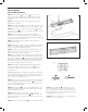
Length L 622mm 1204mm
Breadth B 140mm 140mm
Height H 66mm 66mm
Figure 1