
Datasheet

74HC_HCT2G66 All information provided in this document is subject to legal disclaimers. © NXP B.V. 2013. All rights reserved.
Product data sheet Rev. 10 — 3 October 2013 5 of 23
NXP Semiconductors 74HC2G66; 74HCT2G66
Dual single-pole single-throw analog switch
9. Recommended operating conditions
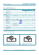
[1] To avoid drawing V
CC
current out of pin nZ, when switch current flows in pin nY, the voltage drop across the bidirectional switch must not
exceed 0.4 V. If the switch current flows into pin nZ, no V
CC
current will flow out of terminal nY. In this case there is no limit for the
voltage drop across the switch, but the voltage at pins nY and nZ may not exceed V
CC
or GND.
10. Static characteristics
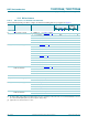
Table 6. Recommended operating conditions
Voltages are referenced to GND (ground = 0 V).
[1]
Symbol Parameter Conditions 74HC2G66 74HCT2G66 Unit
Min Typ Max Min Typ Max
V
CC
supply voltage 2.0 5.0 10.0 4.5 5.0 5.5 V
V
I
input voltage 0 - V
CC
0-V
CC
V
V
O
output voltage 0 - V
CC
0-V
CC
V
V
SW
switch voltage 0 - V
CC
0-V
CC
V
T
amb
ambient temperature 40 +25 +125 40 +25 +125 C
t/V input transition rise
and fall rate
V
CC
= 2.0 V - - 625 - - - ns/V
V
CC
= 4.5 V - 1.67 139 - 1.67 139 ns/V
V
CC
= 6.0 V - - 83 - - - ns/V
V
CC
= 10.0 V - - 35 - - - ns/V
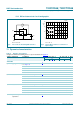
Table 7. Static characteristics
Voltages are referenced to GND (ground = 0 V).
Symbol Parameter Conditions 40 C to +85 C 40 C to +125 C Unit
Min Typ
[1]
Max Min Max
74HC2G66
V
IH
HIGH-level
input voltage
V
CC
= 2.0 V 1.5 1.2 - 1.5 - V
V
CC
= 4.5 V 3.15 2.4 - 3.15 - V
V
CC
= 6.0 V 4.2 3.2 - 4.2 - V
V
CC
= 9.0 V 6.3 4.7 - 6.3 - V
V
IL
LOW-level
input voltage
V
CC
= 2.0 V - 0.8 0.5 - 0.5 V
V
CC
= 4.5 V - 2.1 1.35 - 1.35 V
V
CC
= 6.0 V - 2.8 1.8 - 1.8 V
V
CC
= 9.0 V - 4.3 2.7 - 2.7 V
I
I
input leakage current nE; V
I
=V
CC
or GND
V
CC
=6.0V - - 0.1 - 0.1 A
V
CC
=9.0V - - 0.2 - 0.2 A
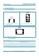
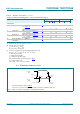
I
S(OFF)
OFF-state
leakage current
nY or nZ; V
CC
= 9.0 V; see Figure 6 - 0.1 1.0 - 1.0 A
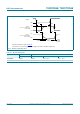
I
S(ON)
ON-state
leakage current
nY or nZ; V
CC
= 9.0 V; see Figure 7 - 0.1 1.0 - 1.0 A
I
CC
supply current nE, nY and nZ = V
CC
or GND
V
CC
=6.0V - - 10 - 20 A
V
CC
=9.0V - - 20 - 40 A