
Datasheet


December 1990 3
Philips Semiconductors Product specification
BCD to 7-segment latch/decoder/driver 74HC/HCT4511
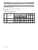
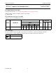
ORDERING INFORMATION
See
“74HC/HCT/HCU/HCMOS Logic Package Information”
.
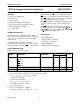
PIN DESCRIPTION
PIN NO. SYMBOL NAME AND FUNCTION
3
LT lamp test input (active LOW)
4
BI ripple blanking input (active LOW)
5
LE latch enable input (active LOW)
7, 1, 2, 6 D
1
to D
4
BCD address inputs
8 GND ground (0 V)
13, 12, 11, 10, 9, 15, 14 Q
a
to Q
g
segments outputs
16 V
CC
positive supply voltage
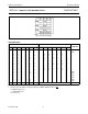
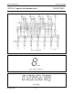
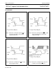
Fig.1 Pin configuration. Fig.2 Logic symbol. Fig.3 IEC logic symbol.