INTEGRATED CIRCUITS DATA SHEET For a complete data sheet, please also download: • The IC06 74HC/HCT/HCU/HCMOS Logic Family Specifications • The IC06 74HC/HCT/HCU/HCMOS Logic Package Information • The IC06 74HC/HCT/HCU/HCMOS Logic Package Outlines 74HC/HCT5555 Programmable delay timer with oscillator Product specification File under Integrated Circuits, IC06 September 1993
Philips Semiconductors Product specification Programmable delay timer with oscillator 74HC/HCT5555 FEATURES GENERAL DESCRIPTION • Positive and negative edge triggered The 74HC/HCT5555 are high-speed Si-gate CMOS devices and are pin compatible with low power Schottky TTL (LSTTL). They are specified in compliance with JEDEC standard no. 7A.
Philips Semiconductors Product specification Programmable delay timer with oscillator 74HC/HCT5555 PINNING SYMBOL PIN DESCRIPTION RS 1 clock input/oscillator pin RTC 2 external resistor connection CTC 3 external capacitor connection A 4 trigger input (positive-edge triggered) B 5 trigger input (negative-edge triggered) RTR/RTR 6 retriggerable/non-retriggerable input (active HIGH/active LOW) Q 7 pulse output (active LOW) GND 8 ground (0 V) Q 9 pulse output (active HIGH) S 0
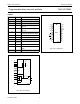
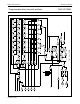
Philips Semiconductors Product specification Programmable delay timer with oscillator handbook, full pagewidth 1 RS 74HC/HCT5555 2 3 10 11 12 13 R TC C TC S0 S1 S2 S3 CP 24 - STAGE COUNTER CD OSC 14 CON POWER-ON RESET 15 MR 4 A 5 B MONOSTABLE CIRCUITRY Q 9 OUTPUT STAGE Q 7 6 RTR/RTR MGA644 Fig.3 Functional diagram. FUNCTIONAL DESCRIPTION The oscillator configuration allows the design of RC or crystal oscillator circuits.
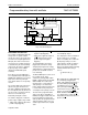
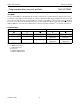
September 1993 S0 S1 S2 S3 OSC CON RS R TC C TC 5 B A ndbook, full pagewidth CP CD Fig.4 Logic diagram.
Philips Semiconductors Product specification Programmable delay timer with oscillator 74HC/HCT5555 TEST MODE Set S3 to a logic LOW level, this will divide the 24 stage counter into three, parallel clocking, 8-stage counters. Set S0, S1 and S2 to a logic HIGH level, this programs the counter to divide-by 28 (256). Apply a trigger pulse and clock in 255 pulses, this sets all flip-flop stages to a logic HIGH level. Set S3 to a logic HIGH level, this causes the counter to divide-by 224.
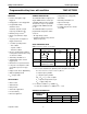
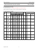
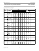
Philips Semiconductors Product specification Programmable delay timer with oscillator 74HC/HCT5555 DELAY TIME SELECTION SELECT INPUTS S3 S2 L OUTPUT Q/Q (FREQUENCY DIVIDING) S1 L S0 L BINARY DECIMAL L 21 2 4 L L L H 22 L L H L 23 8 H 24 16 32 L L H L H L L 25 L H L H 26 64 L 27 128 256 L H H L H H H 28 . . . . . .
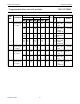
Philips Semiconductors Product specification Programmable delay timer with oscillator 74HC/HCT5555 DC CHARACTERISTICS FOR 74HC For the DC characteristics see “74HC/HCT/HCU/HCMOS Logic Family Specifications”. Output capability: parallel outputs, bus driver; serial output, standard ICC category: MSI. DC CHARACTERISTICS FOR 74HC Tamb (°C) SYMBOL TEST CONDITION +25 −40 to +85 −40 to +125 MIN TYP MAX MIN MAX MIN PARAMETER − − − UNIT MAX VCC (V) VI OTHER − − − 1.9 4.4 5.9 − − − V V V 2.0 4.
Philips Semiconductors Product specification Programmable delay timer with oscillator 74HC/HCT5555 Tamb (°C) SYMBOL VOH +25 −40 to +85 −40 to +125 MIN TYP MAX MIN MAX MIN 3.98 − 5.48 − − − 3.84 − 5.34 − 3.7 5.2 − − V V 4.5 6.0 RS = GND; OSC CON = VCC Io = −2.6 mA Io = −3.3 mA 3.98 − 5.48 − − − 3.84 − 5.34 − 3.7 5.2 − − V V 4.5 6.0 RS = VCC; OSC CON = GND; untriggered Io = −0.65 mA Io = −0.85 mA 1.9 4.4 5.9 2.0 4.5 6 − − − 1.9 4.4 5.9 − − − 1.9 4.4 5.9 − − − V V V 2.0 4.
Philips Semiconductors Product specification Programmable delay timer with oscillator 74HC/HCT5555 AC CHARACTERISTICS FOR 74HC GND = 0 V; tr = tf = 6 ns; CL = 50 pF. Tamb (°C) SYMBOL +25 PARAMETER MIN TYP MAX TEST CONDITION −40 to +85 −40 to +125 MIN MIN MAX UNIT MAX VCC (V) WAVEFORMS tPLH/tPHL propagation delay A, B to Q, Q − − − 77 28 22 240 48 41 − − − 300 60 51 − − − 360 72 61 ns ns ns 2.0 4.5 6.0 Fig.
Philips Semiconductors Product specification Programmable delay timer with oscillator 74HC/HCT5555 Tamb (°C) SYMBOL +25 PARAMETER MIN TYP MAX TEST CONDITION −40 to +85 −40 to +125 MIN MIN MAX UNIT MAX VCC (V) WAVEFORMS fmax maximum clock pulse frequency 2 10 12 5.9 18 21 − − − 1.8 8 10 − − − 1.3 6.6 8 − − − MHz MHz MHz 2.0 4.5 6.0 Fig.8; note 3 fmax maximum clock pulse frequency 6 30 35 24.8 75 89 − − − 4.8 24 28 − − − 4 20 24 − − − MHz MHz MHz 2.0 4.5 6.0 Fig.
Philips Semiconductors Product specification Programmable delay timer with oscillator 74HC/HCT5555 DC CHARACTERISTICS FOR 74HCT For the DC characteristics see “74HC/HCT/HCU/HCMOS Logic Family Specifications”. Output capability: non-standard; bus driver with extended specification on VOH and VOL ICC category: MSI. Tamb (°C) +25 SYMBOL PARAMETER TEST CONDITION −40 to +85 MIN UNIT V CC (V) MAX − 4.4 − V 4.5 Io = −20 µA 3.84 − 3.7 − V 4.
Philips Semiconductors Product specification Programmable delay timer with oscillator 74HC/HCT5555 Tamb (°C) +25 SYMBOL PARAMETER VOH HIGH level output voltage RTC output VOH HIGH level output voltage CTC output VOL LOW level output voltage RTC output VOL LOW level output voltage CTC output TEST CONDITION −40 to +85 −0 to +125 MIN TYP MAX MIN MAX MIN UNIT V CC (V) MAX 3.98 − − 3.84 − 3.7 − V 3.98 − − 3.84 − 3.7 − 4.4 4.5 − 4.4 − 4.4 4.4 4.5 − 4.4 − 3.
Philips Semiconductors Product specification Programmable delay timer with oscillator 74HC/HCT5555 AC CHARACTERISTICS FOR 74HCT GND = 0 V; tr = tf = 6 ns; CL = 50 pF. Tamb (°C) SYMBOL +25 PARAMETER MIN TYP MAX TEST CONDITION −40 to +85 −40 to +125 MIN MIN MAX UNIT MAX VCC (V) WAVEFORMS tPLH/tPHL propagation delay A, B to Q, Q − 28 48 − 60 − 72 ns 4.5 Fig.6 tPHL/tPLH propagation delay MR to Q, Q − 24 41 − 51 − 62 ns 4.5 Fig.
Philips Semiconductors Product specification Programmable delay timer with oscillator 74HC/HCT5555 Notes 1. One stage selected. 2. It is possible to retrigger directly after the trigger pulse, however the pulse will only be extended, if the time period exceeds the clock input cycle time divided by 2. 3. One stage selected. The termination of the output pulse remains synchronized with respect to the falling edge of the RS clock input. 4. One stage selected.
Philips Semiconductors Product specification Programmable delay timer with oscillator 74HC/HCT5555 AC WAVEFORMS tW handbook, full pagewidth 90% VM (1) B INPUT 10% 90% VM (1) A INPUT GND 10% tW t THL t TLH 90% VM (1) Q OUTPUT 10% t PHL t PLH tW 90% Q OUTPUT VM (1) 10% t TLH t THL MGA653 (1) HC : VM = 50%; VI = GND to VCC. HCT: VM = 1.3 V; VI = GND to 3 V. Fig.
Philips Semiconductors Product specification Programmable delay timer with oscillator 74HC/HCT5555 handbook, full pagewidth MR INPUT VM (1) tW t rem A INPUT VM (1) t rem VM (1) B INPUT t PLH VM (1) Q OUTPUT t PHL Q OUTPUT VM (1) MGA652-1 (1) HC : VM = 50%; VI = GND to VCC. HCT: VM = 1.3 V; VI = GND to 3 V. Fig.7 Waveforms showing the master reset (MR) pulse width, the master reset to outputs (Q and Q) propagation delays and the master reset to trigger inputs (A and B) removal time.
Philips Semiconductors Product specification Programmable delay timer with oscillator handbook, full pagewidth 74HC/HCT5555 1/f max RS INPUT 1 2 VCC tW t PHL VM (1) Q OUTPUT t PLH VM (1) Q OUTPUT MGA651 (1) HC : VM = 50%; VI = GND to VCC. HCT: VM = 1.3 V; VI = GND to 3 V. Fig.8 Waveforms showing the clock (RS) to outputs (Q and Q) propagation delays, the clock pulse width and the maximum clock frequency.
Philips Semiconductors Product specification Programmable delay timer with oscillator handbook, full pagewidth 74HC/HCT5555 A INPUT tW B INPUT t rt tW Q OUTPUT tW tW tW MGA650 (1) HC : VM = 50%; VI = GND to VCC. HCT: VM = 1.3 V; VI = GND to 3 V. Fig.10 Output pulse control using retrigger pulse (RTR/RTR = HIGH).
Philips Semiconductors Product specification Programmable delay timer with oscillator 74HC/HCT5555 APPLICATION INFORMATION MBA333 14 handbook, g halfpage fs (mA/V) max. 12 R bias = 560 kΩ handbook, halfpage typ. 10 VCC 8 0.47 µ F min. output 100 µF input 6 vi A io (f = 1 kHz) 4 GND MGA645 2 0 1 2 3 4 5 VCC (V) 6 Fig.12 Typical forward transconductance gfs as a function of the supply voltage at VCC at Tamb = 25 °C. Fig.
Philips Semiconductors Product specification Programmable delay timer with oscillator 74HC/HCT5555 Timing Component Limitations Start-up Using External Clock Termination of the Timing Pulse The oscillator frequency is mainly determined by RtCt, provided R2 ≈ 2Rt and R2C2 << RtCt. The function of R2 is to minimize the influence of the forward voltage across the input protection diodes on the frequency. The stray capacitance C2 should be kept as small as possible.
Philips Semiconductors Product specification Programmable delay timer with oscillator Minimum Output Pulse Width The minimum output pulse width is determined by the minimum clock pulse width, plus the maximum propagation delay of A, B to Q. The rising edge of Q is dominated by the A, B to Q propagation delay, while the falling edge of Q is dominated by RS to Q propagation delay. These propagation delays are not equal.
Philips Semiconductors Product specification Programmable delay timer with oscillator handbook, halfpage 74HC/HCT5555 MR (from logic) 1 RS R TC 2 R bias 100 kΩ to 1 MΩ C3 22 to 37 pF C2 R2 2.2 kΩ 100 pF MLB336 Fig.15 External components configuration for a crystal oscillator. MGA648 40 deviation (%) handbook, full pagewidth 36 32 28 max. expected typ. expected min. expected 24 20 16 12 8 4 0 0 100 200 300 400 500 programmed time (ns) Fig.