
Datasheet


September 1993 10
Philips Semiconductors Product specification
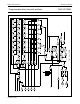
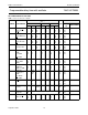
Programmable delay timer with oscillator 74HC/HCT5555
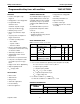
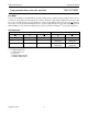
AC CHARACTERISTICS FOR 74HC
GND = 0 V; t
r
= t
f
= 6 ns; C
L
= 50 pF.
SYMBOL PARAMETER
T
amb
(°C)
UNIT
TEST CONDITION
+25 −40 to +85 −40 to +125
V
CC
(V)
WAVEFORMS
MIN TYP MAX MIN MAX MIN MAX
t
PLH
/t
PHL
propagation
delay A, B to
Q, Q
−
−
−
77
28
22
240
48
41
−
−
−
300
60
51
−
−
−
360
72
61
ns
ns
ns
2.0
4.5
6.0
Fig.6
t
PLH
/t
PHL
propagation
delay MR to Q,
Q
−
−
−
61
22
18
185
37
31
−
−
−
230
46
39
−
−
−
280
56
48
ns
ns
ns
2.0
4.5
6.0
Fig.7
t
PLH
/t
PHL
propagation
delay RS to Q,
Q
−
−
−
83
30
24
250
50
43
−
−
−
315
63
54
−
−
−
375
75
64
ns
ns
ns
2.0
4.5
6.0
Fig.8; note 1
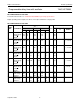
t
THL
/t
TLH
output
transition time
−
−
−
19
7
6
75
15
13
−
−
−
95
19
16
−
−
−
110
22
19
ns
ns
ns
2.0
4.5
6.0
Fig.6
t
W
trigger pulse
width
A = HIGH
B = LOW
70
14
12
17
6
5
−
−
−
90
18
15
−
−
−
105
21
18
−
−
−
ns
ns
ns
2.0
4.5
6.0
Fig.6
t
W
master reset
pulse width
HIGH
70
14
12
19
7
6
−
−
−
90
18
15
− 105
21
18
−
−
−
ns
ns
ns
2.0
4.5
6.0
Fig.7
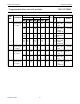
t
W
clock pulse
width RS;
HIGH or LOW
80
16
14
25
9
7
−
−
−
100
20
17
−
−
−
120
24
20
−
−
−
ns
ns
ns
2.0
4.5
6.0
Fig.8
t
W
minimum
output pulse
width
Q = HIGH,
Q = LOW
−
−
−
275
100
80
−
−
−
−
−
−
−
−
−
−
−
−
−
−
−
ns
ns
ns
2.0
4.5
6.0
Fig.6; note 1
t
rt
retrigger time
A, B
−
−
−
0
0
0
−
−
−
−
−
−
−
−
−
−
−
−
−
−
−
ns
ns
ns
2.0
4.5
6.0
Fig.10; note 2
R
EXT
external timing
resistor
5
1
−
−
1000
1000
−
−
−
−
−
−
−
−
−
−
kΩ
kΩ
2.0
5.0
Fig.13
C
EXT
external timing
capacitor
50
50
no limits
pF
pF
2.0
5.0
Fig.13
t
rem
removal time
MR to A, B
120
24
20
39
14
11
−
−
−
150
30
26
−
−
−
180
36
31
−
−
−
ns
ns
ns
2.0
4.5
6.0
Fig.7