
Datasheet


September 1993 6
Philips Semiconductors Product specification
Programmable delay timer with oscillator 74HC/HCT5555
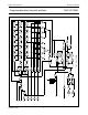
TEST MODE
Set S
3
to a logic LOW level, this will divide the 24 stage counter into three, parallel clocking, 8-stage counters. Set S
0
,
S
1
and S
2
to a logic HIGH level, this programs the counter to divide-by 2
8
(256). Apply a trigger pulse and clock in 255
pulses, this sets all flip-flop stages to a logic HIGH level. Set S
3
to a logic HIGH level, this causes the counter to divide-by
2
24
. Clock one more pulse into the RS input, this causes a logic 0 to ripple through the counter and output Q/Q goes from
HIGH-to-LOW level. This method of testing the delay counter is faster than clocking in 2
24
(16 777 216) clock pulses.
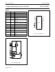
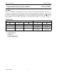
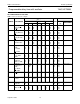
FUNCTION TABLE
Notes
1. H = HIGH voltage level
L = LOW voltage level
X = don't care
↑ = LOW-to-HIGH transition
↓ = HIGH-to-LOW transition.
INPUTS OUTPUTS
MR A
BQQ
HXXLH
L↑X one HIGH level
output pulse
one LOW level
output pulse
LX↓one HIGH level
output pulse
one LOW level
output pulse