
Datasheet


BF1108_BF1108R_4 © NXP B.V. 2008. All rights reserved.
Product data sheet Rev. 04 — 29 May 2008 4 of 10
NXP Semiconductors
BF1108; BF1108R
Silicon RF switches
8. Dynamic characteristics
[1] I
F
= diode forward current.
[2] C
i
is the series connection of C
GS
and C
GK
; C
o
is the series connection of C
GD
and C
GK
.
[3] Guaranteed on AQL basis; inspection level S4, AQL 1.0.
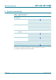
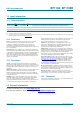
Table 8. Dynamic characteristics
Common cathode; T
amb
= 25
°
C.
Symbol Parameter Conditions Min Typ Max Unit
FET and diode
L
ins(on)
on-state insertion loss V
SK
=V
DK
=0V; I
F
=0mA
[1]
R
S
=R
L
=50Ω; f ≤ 1 GHz - - 2 dB
R
S
=R
L
=50Ω; f = 1 GHz - 1.3 - dB
R
S
=R
L
=75Ω; f ≤ 1 GHz - - 3 dB
ISL
off
off-state isolation V
SK
=V
DK
=5V; I
F
=1mA
R
S
=R
L
=50Ω; f ≤ 1 GHz 30 - - dB
R
S
=R
L
=50Ω; f = 1 GHz - 38 - dB
R
S
=R
L
=75Ω; f ≤ 1 GHz 30 - - dB
R
DSon
drain-source on-state
resistance
V
KS
=0V; I
D
= 1 mA - 12 20 Ω
C
i
input capacitance f = 1 MHz
[2]
V
SK
=V
DK
=5V; I
F
=1mA - 1 - pF
V
SK
=V
DK
=0V; I
F
= 0 mA - 0.65 0.9 pF
C
o
output capacitance f = 1 MHz
[2]
V
SK
=V
DK
=5V; I
F
=1mA - 1 - pF
V
SK
=V
DK
=0V; I
F
= 0 mA - 0.65 0.9 pF
Diode
C
d
diode capacitance f = 1 MHz; V
R
= 0 V - 1.1 - pF
r
D
diode forward resistance I
F
= 2 mA; f = 100 MHz
[3]
- - 0.7 Ω