
Datasheet


BGA7124 All information provided in this document is subject to legal disclaimers. © NXP B.V. 2010. All rights reserved.
Product data sheet Rev. 3 — 9 September 2010 5 of 33
NXP Semiconductors
BGA7124
400 MHz to 2700 MHz 0.25 W high linearity silicon amplifier
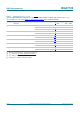
7. Thermal characteristics
[1] defined as thermal resistance from junction to GND paddle.
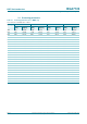
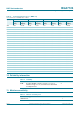
8. Static characteristics
[1] The supply current is adjustable; see Section 8.1 “Supply current adjustment”.
[2] See Section 12 “
Application information”.
8.1 Supply current adjustment
The supply current can be adjusted by changing the value of external ICQ resistor (R2);
(see Figure 4
).
Table 6. Thermal characteristics
Symbol Parameter Conditions Typ Max Unit
R
th(j-mb)
thermal resistance from junction to
mounting base
T
case
=85°C; V
CC
=5V;
I
CC
= 130 mA
[1]
32 - K/W
Table 7. Characteristics
Input and output impedances matched to 50
Ω
, pin SHDN = HIGH (shutdown disabled). Typical
values at V
CC
=3.3V or V
CC
=5V; T
case
=25
°
C; unless otherwise specified.
Symbol Parameter Conditions Min Typ Max Unit
I
CC
supply current V
CC
= 3.3 V
[1]
50 - 200 mA
R1 = 0 Ω; R2 = 1330 Ω
[2]
115 130 145 mA
R1 = 2.2 Ω; R2 = 1070 Ω
[2]
135 160 185 mA
V
CC
= 5.0 V
[1]
50 - 170 mA
R1 = 0 Ω; R2 = 1960 Ω
[2]
110 130 150 mA
R1 = 2.2 Ω; R2 = 1650 Ω
[2]
125 150 175 mA
during shutdown; pin
SHDN
= LOW (shutdown enabled)
-46μA