
Network Device User manual ISP1183

NXP Semiconductors
UM10044
ISP1183 Low-Power USB Peripheral Controller PC Eval Kit
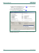
JP4 sets the IRQ number for the ISP1183 eval board. Default setting is IRQ5 as shown
in
Table 3. Short Intx_IRQ and pin 5.
Table 3. JP4
IRQ number IRQ5 (default) IRQ3 IRQ4 IRQ6 IRQ7
Short pins 5 - Intx_IRQ 3 - Intx_IRQ 4 - Intx_IRQ 6 - Intx_IRQ 7 - Intx_IRQ
Jumper JP5 is reserved (left open).
Table 4. S2
Microcontroller power supply 5 V (default) 3.3 V
Short pins 1 - 2 2 - 3
Table 5. S4
Board power supply Bus-powered Self-powered (default)
Short pins 1 - 2 2 - 3
Table 6. S5
V
BUS
power supply Bus-powered (default) Self-powered
Short pins 1 - 2 2 - 3
Table 7. Possible conflict settings
IRQ number Possible conflict
IRQ5 Creative SoundBlaster and compatible sound cards always occupy this IRQ, by
default. If this type of sound card is installed, check its settings or remove it.
Some network cards may also use this IRQ.
IRQ7 Used by parallel port, by default. May cause printing problem on peripheral PC.
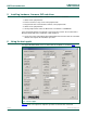
4. I/O mapping
The ISP1183 eval board occupies eight I/O locations. The base address is 368h.
Table 8. I/O mapping
Offset Usage
0 ISP1183 data register, read or write
1 Write command register, read data bus state
2 Board control and read chip I/O state
3 Reserved
4 to 7 Reserved for expansion board
UM10044_4 © NXP B.V. 2007. All rights reserved.
User manual Rev. 04 — 6 February 2007 5 of 18