
Datasheet

KMZ60 All information provided in this document is subject to legal disclaimers. © NXP B.V. 2014. All rights reserved.
Product data sheet Rev. 2 — 7 February 2014 3 of 30
NXP Semiconductors
KMZ60
Angle sensor with integrated amplifier
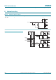
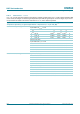
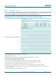
4. Functional diagram
5. Functional description
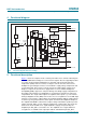
Figure 1 shows the complete circuit consisting of the MR sensor element realized by two
interleaved Wheatstone bridges for cosine and sine signals. Also the supporting functions
for control circuit and signal amplification are included. A Proportional To Absolute
Temperature (PTAT) reference current, a voltage-to-current converter and a current
multiplier are generating the reference current which is supply voltage, temperature and
resistor dependent. This reference current controls the supply voltage of both sensor
bridges to compensate their TC via a supply buffer. For noise and ElectroMagnetic
Compatibility (EMC) suppression low-pass filtering of the bridge supply is implemented.
The bridge output voltages are amplified by a constant factor and fed to the rail-to-rail
output buffers. The single-ended outputs are capable to drive inputs e.g. of an external
Analog-to-Digital Converter (ADC) referenced to V
CC
. For an optimal use of the ADC input
range the cosine and sine output voltages are tracking ratiometric with the supply voltage.
To achieve good signal performance, both signals are matched in amplitude and phase.
The amplifier bandwidth is sufficient for low phase delay at maximum specified speed of
rotation. Pin TCC_EN is used to enable the temperature compensation. Two modes are
defined. The TC of the MR sensor signal amplitude is largely compensated by the
amplifier if pin TCC_EN is connected to V
CC
. The amplified sensor signal, which has
a negative TC, is available at the output pins VOUT1 and VOUT2 if pin TCC_EN is
Fig 1. Functional diagram with sensor bridge
001aan885
R
B
R
1
R
2
R
3
C
3
FUNCTIONAL
CONTROL
BROKEN
BOND WIRE
DETECTION
TEMPERATURE
SENSOR
GNDS
V
CC
V
CC
TCC_EN
POWERDOWN_EN
VOUT1
VOUT2
VTEMP
GND
VDDS
VDDS
CURRENT
MULTIPLIER
U / I
PTAT
REF
VcosI
TC_comp
I
PTAT
I
const
I = f(V
CC
, T
amb
, R
2
)
I
T
= f(T
amb
)
I
V
= f(V
CC
) TC comp
enable
VIN1P
MR
SENSOR
R
B
Vsin
GAIN = 6
GAIN = 6
GAIN = 7
GAIN = 7
BUFFER
VIN1N
V
CC
/ 2
VIN2P
VIN2N