
Datasheet

LM75B All information provided in this document is subject to legal disclaimers. © NXP B.V. 2015. All rights reserved.
Product data sheet Rev. 6.1 — 6 February 2015 6 of 37
NXP Semiconductors
LM75B
Digital temperature sensor and thermal watchdog
In OS comparator mode, the OS output behaves like a thermostat. It becomes active
when the Temp exceeds the T
th(ots)
, and is reset when the Temp drops below the T
hys
.
Reading the device registers or putting the device into shutdown does not change the
state of the OS output. The OS output in this case can be used to control cooling fans or
thermal switches.
In OS interrupt mode, the OS output is used for thermal interruption. When the device is
powered-up, the OS output is first activated only when the Temp exceeds the T
th(ots)
; then
it remains active indefinitely until being reset by a read of any register. Once the OS output
has been activated by crossing T
th(ots)
and then reset, it can be activated again only when
the Temp drops below the T
hys
; then again, it remains active indefinitely until being reset
by a read of any register. The OS interrupt operation would be continued in this sequence:
T
th(ots)
trip, Reset, T
hys
trip, Reset, T
th(ots)
trip, Reset, T
hys
trip, Reset, etc. Putting the
device into the shutdown mode by setting the bit 0 of the configuration register also resets
the OS output.
In both cases, comparator mode and interrupt mode, the OS output is activated only if a
number of consecutive faults, defined by the device fault queue, has been met. The fault
queue is programmable and stored in the two bits, B3 and B4, of the Configuration
register. Also, the OS output active state is selectable as HIGH or LOW by setting
accordingly the configuration register bit B2.
At power-up, the device is put into normal operation mode, the T
th(ots)
is set to 80 C, the
T
hys
is set to 75 C, the OS active state is selected LOW and the fault queue is equal to 1.
The temp reading data is not available until the first conversion is completed in about
100 ms.
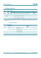
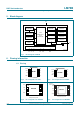
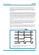
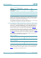
The OS response to the temperature is illustrated in Figure 6
.
(1) OS is reset by either reading register or putting the device in shutdown mode. It is assumed that
the fault queue is met at each T
th(ots)
and T
hys
crossing point.
Fig 6. OS response to temperature
002aae334
(1) (1) (1)
T
th(ots)
T
hys
OS reset
OS active
OS reset
OS active
OS output in comparator mode
OS output in interrupt mode
reading temperature limits