
Datasheet


PCF2127AT All information provided in this document is subject to legal disclaimers. © NXP B.V. 2013. All rights reserved.
Product data sheet Rev. 6 — 11 July 2013 6 of 86
NXP Semiconductors
PCF2127AT
Integrated RTC, TCXO and quartz crystal
8. Functional description
The PCF2127AT is a Real Time Clock (RTC) and calendar with an on-chip Temperature
Compensated Crystal (Xtal) Oscillator (TCXO) and a 32.768 kHz quartz crystal integrated
into the same package (see Section 8.3.2
).
Address and data are transferred by a selectable 400 kHz Fast-mode I
2
C-bus or a 3 line
SPI-bus with separate data input and output (see Section 9
). The maximum speed of the
SPI-bus is 6.5 Mbit/s.
The PCF2127AT has a backup battery input pin and backup battery switch-over circuit
which monitors the main power supply. The backup battery switch-over circuit
automatically switches to the backup battery when a power failure condition is detected
(see Section 8.6.1
). Accurate timekeeping is maintained even when the main power
supply is interrupted.
A battery low detection circuit monitors the status of the battery (see Section 8.6.3
). When
the battery voltage drops below a certain threshold value, a flag is set to indicate that the
battery must be replaced soon. This ensures the integrity of the data during periods of
battery backup.
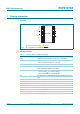
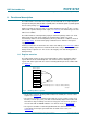
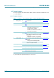
8.1 Register overview
The PCF2127AT contains an auto-incrementing address register: the built-in address
register will increment automatically after each read or write of a data byte up to the
register 1Bh. After register 1Bh, the auto-incrementing will wrap around to address 00h
(see Figure 3
).
• The first three registers (memory address 00h, 01h, and 02h) are used as control
registers (see Section 8.2
).
• The registers at addresses 03h through to 09h are used as counters for the clock
function (seconds up to years). The date is automatically adjusted for months with
fewer than 31 days, including corrections for leap years. The clock can operate in
12-hour mode with an AM/PM indication or in 24-hour mode (see Section 8.9
).
• The registers at addresses 0Ah through 0Eh define the alarm function. It can be
selected that an interrupt is generated when an alarm event occurs (see
Section 8.10
).
Fig 3. Handling address registers
001aaj307
address register
00h
auto-increment
wrap around
01h
02h
03h
...
19h
1Ah
1Bh
1Ch
1Dh not reachable by auto-inc. - needs to be addressed directly
not reachable by auto-inc. - needs to be addressed directly