
Datasheet

PCF85063TP All information provided in this document is subject to legal disclaimers. © NXP B.V. 2013. All rights reserved.
Product data sheet Rev. 3 — 11 July 2013 6 of 47
NXP Semiconductors
PCF85063TP
Tiny Real-Time Clock/calendar
8.2 Control registers
8.2.1 Register Control_1
[1] Default value.
[2] For a software reset, 01011000 (58h) must be sent to register Control_1 (see Section 8.2.1.3
).
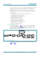
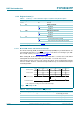
8.2.1.1 EXT_TEST: external clock test mode
A test mode is available which allows for on-board testing. In this mode, it is possible to
set up test conditions and control the operation of the RTC.
The test mode is entered by setting bit EXT_TEST in register Control_1. Then
pin CLKOUT becomes an input. The test mode replaces the internal clock signal with the
signal applied to pin CLKOUT.
The signal applied to pin CLKOUT should have a minimum pulse width of 300 ns and a
maximum period of 1000 ns. The internal clock, now sourced from CLKOUT, is divided
down to 1 Hz by a 2
6
divide chain called a prescaler. The prescaler can be set into a
known state by using bit STOP. When bit STOP is set, the prescaler is reset to 0. (STOP
must be cleared before the prescaler can operate again.)
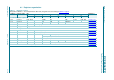
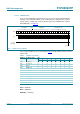
Table 6. Control_1 - control and status register 1 (address 00h) bit description
Bit Symbol Value Description Reference
7 EXT_TEST external clock test mode Section 8.2.1.1
0
[1]
normal mode
1 external clock test mode
6 - 0 unused -
5STOP STOP bit Section 8.2.1.2
0
[1]
RTC clock runs
1 RTC clock is stopped; all RTC divider chain
flip-flops are asynchronously set logic 0
4SR software reset Section 8.2.1.3
0
[1]
no software reset
1 initiate software reset
[2]
; this bit always
returns a 0 when read
3 - 0 unused -
2CIE correction interrupt enable Section 8.2.3
0
[1]
no correction interrupt generated
1 interrupt pulses are generated at every
correction cycle
1 12_24 12 or 24 hour mode Section 8.3.3
0
[1]
24 hour mode is selected
1 12 hour mode is selected
0 CAP_SEL internal oscillator capacitor selection for
quartz crystals with a corresponding load
capacitance
-
0
[1]
7 pF
1 12.5 pF