
Datasheet

PCF85063TP All information provided in this document is subject to legal disclaimers. © NXP B.V. 2013. All rights reserved.
Product data sheet Rev. 3 — 11 July 2013 7 of 47
NXP Semiconductors
PCF85063TP
Tiny Real-Time Clock/calendar
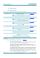
From a stop condition, the first 1 second increment will take place after 32 positive edges
on pin CLKOUT. Thereafter, every 64 positive edges cause a 1 second increment.
Remark: Entry into test mode is not synchronized to the internal 64 Hz clock. When
entering the test mode, no assumption as to the state of the prescaler can be made.
Operation example:
1. Set EXT_TEST test mode (register Control_1, bit EXT_TEST = 1)
2. Set STOP (register Control_1, bit STOP = 1)
3. Clear STOP (register Control_1, bit STOP = 0)
4. Set time registers to desired value
5. Apply 32 clock pulses to pin CLKOUT
6. Read time registers to see the first change
7. Apply 64 clock pulses to pin CLKOUT
8. Read time registers to see the second change
Repeat 7 and 8 for additional increments.
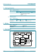
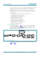
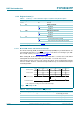
8.2.1.2 STOP: STOP bit function
The function of the STOP bit (see Figure 4
) is to allow for accurate starting of the time
circuits. The STOP bit function causes the upper part of the prescaler (F
2
to F
14
) to be
held in reset and thus no 1 Hz ticks are generated. It also stops the output of clock
frequencies lower than 8 kHz on pin CLKOUT.
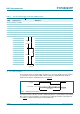
The time circuits can then be set and do not increment until the STOP bit is released (see
Figure 5
and Table 7).
Fig 4. STOP bit functional diagram
DDD
26&,//$725
26&,//$7256723
'(7(&725
VHWWLQJWKH26IODJ
)
+] +] +] +] +]
672
3
+]WLFN
)
)
5(6(7
)
5(6(7
)
5(6(7