
Datasheet

PCF85063TP All information provided in this document is subject to legal disclaimers. © NXP B.V. 2013. All rights reserved.
Product data sheet Rev. 3 — 11 July 2013 8 of 47
NXP Semiconductors
PCF85063TP
Tiny Real-Time Clock/calendar
[1] F
0
is clocked at 32.768 kHz.
The lower two stages of the prescaler (F
0
and F
1
) are not reset. And because the I
2
C-bus
is asynchronous to the crystal oscillator, the accuracy of restarting the time circuits is
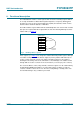
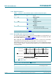
between zero and one 8.192 kHz cycle (see Figure 5
).
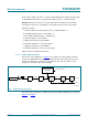
The first increment of the time circuits is between 0.507813 s and 0.507935 s after STOP
bit is released. The uncertainty is caused by the prescaler bits F
0
and F
1
not being reset
(see Table 7
) and the unknown state of the 32 kHz clock.
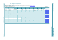
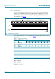
Table 7. First increment of time circuits after STOP bit release
Bit Prescaler bits
[1]
1Hz tick Time Comment
STOP F
0
F
1
-F
2
to F
14
hh:mm:ss
Clock is running normally
0
01-0 0001 1101 0100
12:45:12 prescaler counting normally
STOP bit is activated by user. F
0
F
1
are not reset and values cannot be predicted externally
1
XX-0 0000 0000 0000
12:45:12 prescaler is reset; time circuits are frozen
New time is set by user
1
XX-0 0000 0000 0000
08:00:00 prescaler is reset; time circuits are frozen
STOP bit is released by user
0
XX-0 0000 0000 0000
08:00:00 prescaler is now running
XX-1 0000 0000 0000
08:00:00 -
XX-0 1000 0000 0000
08:00:00 -
XX-1 1000 0000 0000
08:00:00 -
:
::
11-1 1111 1111 1110
08:00:00 -
00-0 0000 0000 0001
08:00:01 0 to 1 transition of F
14
increments the time circuits
10-0 0000 0000 0001
08:00:01 -
:
::
11-1 1111 1111 1111
08:00:01 -
00-0 0000 0000 0000
08:00:01 -
10-0 0000 0000 0000
08:00:01 -
:
::
11-1 1111 1111 1110
08:00:01 -
00-0 0000 0000 0001
08:00:02 0 to 1 transition of F
14
increments the time circuits
DDD
V
WR
V
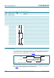
Fig 5. STOP bit release timing
DDD
VWRV
+]
VWRSUHOHDVHG