
Datasheet


PCF8523 All information provided in this document is subject to legal disclaimers. © NXP B.V. 2013. All rights reserved.
Product data sheet Rev. 6 — 17 September 2013 9 of 78
NXP Semiconductors
PCF8523
Real-Time Clock (RTC) and calendar
8.2 Control and status registers
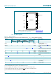
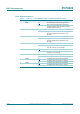
8.2.1 Register Control_1
[1] Default value.
[2] Must always be written with logic 0.
[3] For a software reset, 01011000 (58h) must be sent to register Control_1 (see Section 8.3
). Bit SR always
returns 0 when read.
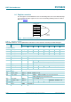
Table 7. Control_1 - control and status register 1 (address 00h) bit description
Bit Symbol Value Description
7 CAP_SEL internal oscillator capacitor selection for quartz
crystals with a corresponding load capacitance
0
[1]
7pF
112.5pF
6T 0
[1][2]
unused
5STOP 0
[1]
RTC time circuits running
1 RTC time circuits frozen;
RTC divider chain flip-flops are
asynchronously set logic 0;
CLKOUT at 32.768 kHz, 16.384 kHz, or
8.192 kHz is still available
4SR 0
[1][3]
no software reset
1 initiate software reset
3 12_24 0
[1]
24 hour mode is selected
1 12 hour mode is selected
2SIE 0
[1]
second interrupt disabled
1 second interrupt enabled
1AIE 0
[1]
alarm interrupt disabled
1 alarm interrupt enabled
0CIE 0
[1]
no correction interrupt generated
1 interrupt pulses are generated at every
correction cycle (see Section 8.8
)