
Datasheet


PCF8563 All information provided in this document is subject to legal disclaimers. © NXP B.V. 2012. All rights reserved.
Product data sheet Rev. 10 — 3 April 2012 9 of 50
NXP Semiconductors
PCF8563
Real-time clock/calendar
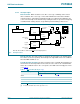
8.3.2.1 Interrupt output
Bits TF and AF: When an alarm occurs, AF is set to logic 1. Similarly, at the end of a
timer countdown, TF is set to logic 1. These bits maintain their value until overwritten
using the interface. If both timer and alarm interrupts are required in the application, the
source of the interrupt can be determined by reading these bits. To prevent one flag being
overwritten while clearing another, a logic AND is performed during a write access.
Bits TIE and AIE: These bits activate or deactivate the generation of an interrupt when
TF or AF is asserted, respectively. The interrupt is the logical OR of these two conditions
when both AIE and TIE are set.
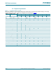
Countdown timer interrupts: The pulse generator for the countdown timer interrupt uses
an internal clock and is dependent on the selected source clock for the countdown timer
and on the countdown value n. As a consequence, the width of the interrupt pulse varies
(see Table 7
).
[1] TF and INT become active simultaneously.
[2] n = loaded countdown value. Timer stops when n = 0.
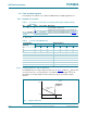
When bits TIE and AIE are disabled, pin INT
will remain high-impedance.
Fig 6. Interrupt scheme
013aaa087
TE
COUNTDOWN COUNTER
AF: ALARM
FLAG
CLEAR
SET
to interface:
read AF
0
1
TF: TIMER
CLEAR
SET
PULSE
GENERATOR 2
CLEAR
TRIGGER
TIE
INT
from interface:
clear TF
from interface:
clear AF
set alarm
flag AF
to interface:
read TF
TI_TP
AIE
e.g. AIE
0
1
Table 7. INT operation (bit TI_TP = 1)
[1]
Source clock (Hz) INT period (s)
n=1
[2]
n>1
[2]
4096
1
⁄
8192
1
⁄
4096
64
1
⁄
128
1
⁄
64
1
1
⁄
64
1
⁄
64
1
⁄
60
1
⁄
64
1
⁄
64