
User's Manual


NXP Semiconductors
UM10301
User Manual PCF85x3, PCA8565 and PCF2123, PCA2125
UM10301_1 © NXP B.V. 2008. All rights reserved.
User manual Rev. 01 — 23 December 2008 43 of 52
17. First period inaccuracy when using the timer
This chapter describes why the programmed delay is not always exactly as expected and
what to do in order to be as accurate as possible. The enable instruction for the timer is
generated by the I
2
C or SPI interface clock. This clock is asynchronous to the timer
source clock. The timer source clock is derived from the 32.768 kHz crystal frequency.
The consequences will be described here.
The RTCs for which this user manual was written include a countdown timer function,
except PCF8583 and PCF8593. The 8-bit countdown timer is controlled by the timer
control register. The timer control register determines one of 4 source clock frequencies
for the timer (4096 Hz, 64 Hz, 1 Hz or 1/60 Hz), and enables or disables the timer.
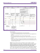
Table 10. Timer delays
Range of possible timer delays dependent on selected source clock frequency and n
Timer Source clock frequency
[1]
delay for n = 1 delay for n = 255
4096 Hz 244 μs 62.256 ms
64 Hz 15.625 ms 3.984 s
1 Hz 1 s 255 s
1/60 Hz 60 s 4 hrs 15 min
[1] If the timer is not used, set source clock frequency to 1/60 Hz for power saving
Remark: Note that all timings which are generated from the 32.768 kHz oscillator are
based on the assumption that there is 0 ppm deviation. Deviation in oscillator frequency
will result in deviation in timings.
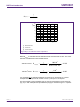
001aaf906
n
duration of first timer period after
enable may range from n − 1 to n + 1
03xx 02 01 03 02 01 03 02 01 03
n
03xxcountdown value, n
timer source clock
countdown counter
TE
TF
INT
In the example it is assumed that the timer flag is cleared before the next countdown period
expires and that the
INT is set to pulsed mode
Fig 20. General countdown timer behaviour