
Datasheet


Analog Integrated Circuit Device Data
Freescale Semiconductor 5
34671
ELECTRICAL CHARACTERISTICS
STATIC ELECTRICAL CHARACTERISTICS
STATIC ELECTRICAL CHARACTERISTICS
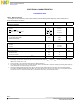
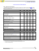
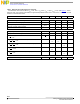
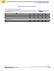
Table 3. Static Electrical Characteristics
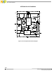
Characteristics noted under conditions V
IN
= 5.0V, -40°C ≤ T
A
≤ 85°C, C
IN
= 1.0µF, C
OUT
= 2.2µF (see Figure 1), unless
otherwise noted. Typical values noted reflect the approximate parameter means at V
IN
= 5.0V and T
A
= 25°C under nominal
conditions, unless otherwise noted.
Characteristic Symbol Min Typ Max Unit
POWER INPUT
Input Voltage Range
(5)
V
IN
2.6
- 10
V
VIN Pin Supply Current
Charger enabled
(6)
Charger disabled
I
IN
-
-
1400
-
-
350
µA
Regulated Output Voltage
V
IN
= 5.0V; I
BAT
= 10mA; T
A
= 25°C
V
IN
= 5.0V; I
BAT
= 10mA; T
A
= -20 to 70°C
V
IN
= 5.0V; I
BAT
= 10mA; T
A
= -40 to 85°C
V
BAT
4.185
4.170
4.158
4.20
4.20
4.20
4.215
4.230
4.230
V
Power MOSFET On Resistance
V
BAT
= 4V; I
BAT
= 500mA; I
CHG
= 600mA
R
DS(ON)
- 500 700
mΩ
BAT Pin Standby Current
VIN not powered or charger disabled
I
STDBY
- - 1.0
µA
Power On Reset
Rising V
IN
threshold
Falling V
IN
threshold
V
POR
3.0
-
-
2.4
3.9
2.6
V
VIN-BAT Offset Voltage
Rising threshold
Falling threshold
V
OS
-
1.0
-
-
60
22
mV
Over-voltage Protection Rising Threshold
V
OVP
10 11 12 V
Over-voltage Protection Threshold Hysteresis
V
OVPHYS
- 400 - mV
CHARGE CURRENT
Constant Current Mode Charge Current Range
(7)
I
CHG
50 - 600 mA
I
CHG
Accuracy
For I
CHG
between 300mA to 600mA
(7)
For I
CHG
between 50mA to 300mA (Tested at 300mA)
I
CHG
95
90
100
100
105
110
%
Trickle-mode Charge Current
I
TRKL
16 20 24 % I
CHG
End-of-Charge (EOC) Threshold
When I
CHG
is set to 300mA
I
EOC
20 30 40
mA
ISET Pin Voltage for I
CHG
Reference
(7)
V
ISET
- 1.0 - V
Notes
5. Refer to the Power-on-Reset parameter for V
IN
turn on and turn off values.
6. Supply current does not include the current delivered to the battery through the BAT pin.
7. Not tested. Guaranteed by design.