
Other Content


PC535 PC625
PC545
PC925
PC1200L
65-PC1750
PC310
PC680
Better warranty
Limited 2-year full replacement warranty — not pro rata.
Longer service life
With 3-10 years of service life, ODYSSEY
®
batteries save
consumers time, money, and aggravation.
Longer cycle life
70% longer cycle life compared to conventional deep
cycle batteries — up to 400 cycles at 80% depth of
discharge — high stable voltage for longer periods of time.
Longer shelf life
Can be stored on open circuit (nothing connected to the
terminals) without the need for recharging up to 2 years
or 12.00V, whichever occurs first.
Faster recharge
The highest recharge efficiency of any sealed lead battery
on the market — capable of 100% recharge in 4 - 6 hours.
Mounting exibility
Non-spillable design — can be mounted on any side in
any position except inverted.
Vibration resistance
Design protects against high impact shock and
mechanical vibration — a common cause of premature
battery failure.
Extreme temperature tolerant
Operating temperatures from -40°C (-40°F) to 45°C
(113ºF) for models without a metal jacket and from -40ºC
(-40ºF) to 80ºC (176ºF) for models with a metal jacket.
Totally maintenance free
No need to add water, ever! Drycell design with
resealable venting system.
Improved safety
US Department of Transportation classified as
a ‘non-spillable’ battery. No acid spills, no
escaping gases.
*Cold Start Performance S.A.E J537 JUNE 82 **Pulse Current
† Can be fitted with brass automotive terminal.
Operating temperature range:
-40°C (-40°F) to 45°C (113°F) without metal jacket
-40ºC (-40ºF) to -80ºC (176ºF) with metal jacket
PC310: -30ºC (-22ºF) to 40ºC (104ºF)
Constant voltage portable charger parameters:
Standby, per 12V battery 13.5-13.8V no current limit required
Cyclic, per 12V battery (16-hour recharge) 14.4-14.8V no current limit required
Typical deep-cycle life at 25°C/77°F at a 5-hour rate 400 cycles at 80% DOD
Typical service life at 25°C/77°F Medium to heavy duty usage – 3+ years
Light duty usage – 6+ years
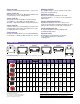
Drawing sizes are for terminal position reference only; diagrams are not proportionate to each other.
† † Optional Metal Jacket (MJ)
Terminal layouts
MODEL
Voltage
PHCA**
(5 sec)
CCA* HCA MCA
Nominal Capacity
Reserve
Capacity
Minutes
Length
inches
(mm)
Width
inches
(mm)
Height
inches
(mm)
Weight
lbs
(kg)
Terminal
Torque
Specs
in-lbs
(Nm max)
Internal
Resistance
(m
Ω
)
Short
Circuit
Current
(20 Hr
Rate-Ah)
(10 Hr
Rate-Ah)
PC310
12 310 100 200 155 8 7 9
5.43
(138.0)
3.39
(86.0)
3.98
(101.0)
5.9
(2.7)
M4
Receptacle
8.9
(1.0)
27.1 455A
PC535
12 535 200 300 265 14 13 21
6.70
(170.2)
3.90
(99.1)
6.18
(157.0)
12.0
(5.4)
M6
Stud
40
(4.5)
8 1000A
PC545
12 545 185 300 240 13 12 18
7.00
(177.8)
3.38
(85.9)
5.17
(131.3)
12.6
(5.7)
M6
Receptacle
50
(5.6)
10 1200A
PC625
12 625 265 440 350 18 17 27
6.70
(170.2)
3.90
(99.1)
6.89
(175.0)
13.2
(6.0)
M6
Stud
40
(4.5)
7 1800A
PC680
12 680 220 370 300 16 16 24
7.27
(184.7)
3.11
(79.0)
6.67
(169.4)
15.4
(7.0)
M6
Receptacle
†
or SAE
3/8”
Receptacle
50
(5.6)
7 1800A
PC925
12 925 380 625 500 28 27 52
6.64
(168.6)
7.05
(179.0)
5.04
(128.0)
26.0
(11.8)
M6
Receptacle
†
or SAE
3/8”
Receptacle
60
(6.8)
5 2400A
† † † †
† †