
Owner manual


A
B
C
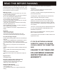
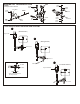
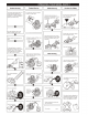
CHECKING ENGINE THROTTLE
* Insert into transmitter.
1. Insert AA batteries into
transmitter (8 Pcs).
2.Turn on transmitter.
3.Turn on receiver.
4.Center throttle trims as
shown .
A
B
C
1. Pull Full Throttle.
1. Push trigger to full
brake position.
2. Adjust alum. Stopper to
increase or decrease
the brake.
Idle Position (A)
Brake ©
Full Throttle (B)
* Align throttle servo same
as shown.
A
B
C
• Full brake arm position.
Spring compresses
forward and brake rods
pull brake levers.
• Full throttle arm position.
Spring rod pulls throttle
barrel open and brake
rods release pressure on
brake cams.
IMPORTANT
CHECK RADIO THROTTLE
AND STEERING SWITCHES
BEFORE RUNNING CAR
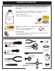
3 x 10mm
Tapping Screw
#10016
Air Filter
Sponge
Refills
#10017 - Blue
#10018 - Yellow
#10019 - Rose
Foam Air filters Unit
#10021 - Black
#10027 - Yellow
#10028 - Pink
#10029 - Blue
Air Filter Connector
Nylon Strap
( Small )
Nylon Strap
( Small )
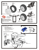
ASSEMBLY OF THE AIR FILTER
You must oil foam filter before use.
Filter will not work if not oiled.
Clean with soap and water only.
You will damage foam if washed
if fuel!
#10015, Foam
Filter oil, Very
Sticky....$9.95
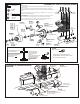
3 X 8mm
Washer
3mm Nylon
Locknut
3 x 5mm Screw
3 x 20mm
Cap Screw
* Place the clutch shoes
with the clutch springs
over the 3 pins of the
flywheel.
Using a screw driver as a lever,
bend the small end of the
clutch spring behind the
clutch nut and press
down to snap shoe in
place.
* Fit the flywheel using a cross
wrench or deep socket.
If engine turns when tightening,
hold piston with large thick tie-wraps
and hard wood in exhaust port.
Do not use metal, it will
damage engine.
#10098
SG Nut & Shim KiT
Engines with ground shafts and few threads
are called SG Shaft. A special clutch nut is needed.
The stock flywheel (#10040) is fine.
ASSEMBLY OF THE CLUTCH INTO ENGINE
#10100
Clutch Spring
#10010
Clutch Shoes
Black Type
* Shoes are
trailing.
3 x 8mm
Washer
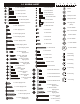
Misc. Hardware
#10099
#34110
5x10x4mm
Ball Bearing
#34110
5x10x4mm
Ball Bearing
#10040 (stock)
3 Pin
Flywheel, Taper
#10041
3 Pin
Flywheel, Hole
#10091
Clutch Nut
screw type
3 x 5mm
Screw
#10330
Brass, Corn (big hole)
#10329
Brass, Corn (sml hole)
3mm
Nylon Lock
Nut
3mm
Nylon Lock
Nut
3 x 20mm
Hex Screw
3 x 20mm
Hex Screw
#30480
Engine Mount
#10398 - 12T
#10399 - 13T
#10400 - 14T (stock)
#10401 - 15T
#10402 - 16T
#10403 - 17T
#10404 - 18T
Clutch Bells
SEE NOTES ABOVE
Notes:
Non-Pull Start Engines...
• Alum. Washer behind the flywheel is not needed when using Force engines or similar types. O.S. Engines will
require washer spacer.
• To check!..place the brass corn #10330 (big hole) against the engine bearing, then flywheel. You should be
covering one or two thread of the engine shaft. If this is the case, you do not need an additional washer behind the
flywheel.
You must cut the engine shaft if too long. Count 6 threads in front of the flywheel and mark. This is all you need to
tighten the clutch nut and mount the flywheel.
Force Pull Start Engine...
• Force Pull Start Engines required NO additional spacer and no shaft cutting. The Force engines comes with an
alum. cast driver washer, you use this part as the spacer, not the alum. washer shown for O.S. installs
But, you must find the #10329 brass corn (sml hole) for Flywheel. This special corn fits the smaller thread
diameter of the engine shaft. It will center the flywheel when tightening the clutch nut.
*Tighten the strap
and cut off the excess.
#10184
Blue, Silicone Tube
#10069
Manifold Adapter
( Red Silicone )
#10120
Manifold
Spring
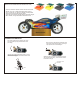
ASSEMBLY OF THE MANIFOLD AND
MUFFLER
Nylon Strap
( Large )
#31991
Manifold, Polished
#10079
Alum. CNC
Pressure Nipple
#31992
Dual Chamber, Polished
* Drill a hole (Size 3.5mm)
in the place and align as shown.
Use a two part high temp. epoxy glue to
fully seal the nipple base.