ARYAL S1 E DUAL INVERTER 14 DUAL INVERTER 18 ISTRUZIONI PER USO E MANUTENZIONE IT INSTRUCTION FOR USE AND MAINTENANCE EN MODE D’EMPLOI ET D’ENTRETIEN FR HINWEISE FÜR DIE VERWENDUNG UND PFLEGE DE INSTRUCCIONES PARA EL USO Y EL MANTENIMIENTO ES MANUAL DE INSTALAÇÃÕ INSTRUÇÕES DE USO E MANUTENÇÃÕ PT AANWIJZINGEN VOOR DE INSTALLATIE, HET GEBRUIK EN HET ONDERHOUD NL GR Attenzione: rischio di incendio Caution: Attention : risque d'incendie Achtung: Brandrisiko Atención: riesgo de incendio Atenção
IT AVVERTENZE 3. Prestare attenzione al fatto che il refrigerante R32 è inodore. dei pericoli ad esso inerenti. dal produttore. EN WARNINGS 3.
FR AVERTISSEMENTS 4. par des enfants sans surveillance. 15. Ne pas percer ou trouer. DE WARNHINWEISE 4. 7. 13.
ES ADVERTENCIAS 4. 7. 15. No perforar. PT ADVERTÊNCIAS 4. 7. 13. 15. Não furar.
WAARSCHUWINGEN NL 9. GR 4.
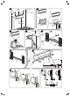
1 min 150mm min 120mm 2 min 120mm min.
10 11 A B C E D F 12 13 14 15 16 6 5 5 17 90° 1 1 3 B A 2 A 2
19 20 a b 21 OK! 23 E D 22 C 24 B 20 25 min.
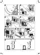
29a 23 W 1(L) 2(N) 30 S 25 21 29 28 24 26 22 27 30 28 31 32 33 E A G B ~8m C D F
34 35 36 4 2 9 1 7 5 8 10 3 6 11 37 4 39 40 41 click !
42 43 a b 44 45 46 47
50 N L(A) N(A) S(A) L L(B) N(B) S(B) POWER DUAL INVERTER 14 DUAL INVERTER 18 1x2 W 1(L) 2(N) S TO “B” W 1(L) 2(N) S TO “A”
0 - AVVERTENZE ............................................................................................................................ 3 0.1 INFORMAZIONI GENERALI ...........................................................................................................3 0.2 SIMBOLOGIA ..................................................................................................................................3 0.2.1 - Pittogrammi redazionali ........................................................
ITALIANO 3.1.2 - Sostituzione delle batterie .............................................................................................................27 3.1.3 - Posizione del telecomando ...........................................................................................................28 3.2 COMPONENTI DEL SISTEMA .....................................................................................................28 3.3 INDICATORE DI FUNZIONE SUL DISPLAY DELL’UNITA’ INTERNA.....................
INDICE GENERALE ITALIANO ILLUSTRAZIONI Le illustrazioni sono raggruppate nelle pagine iniziali del manuale Indice L’indice generale del presente manuale 0 - AVVERTENZE 0.1 - INFORMAZIONI GENERALI Desideriamo innanzitutto ringraziarVi per aver deciso di accordare la vostra preferenza ad un apparecchio di nostra produzione. Documento riservato ai termini di legge con divieto di riproduzione o di trasmissione a terzi senza esplicita autorizzazione della ditta costruttrice.
ITALIANO TENSIONE ELETTRICA PERICOLOSA Segnala al personale interessato che l’operazione descritta presenta, se non effettuata nel rispetto delle normative di sicurezza, il rischio di subire uno shock elettrico.
È SEMPRE NECESSARIO SEGUIRE PRECAUZIONI DI SICUREZZA DI BASE 1. Documento riservato ai termini di legge con divieto di riproduzione o di trasmissione a terzi senza esplicita autorizzazione della ditta OLIMPIA SPLENDID. Le macchine possono subire aggiornamenti e quindi presentare particolari testi contenuti in questo manuale. 2. Leggere attentamente il presente manuale prima di procedere con qualsiasi a quanto descritto nei singoli capitoli. 3.
ITALIANO 10. Eseguire le operazioni di installazione e manutenzione utilizzando 11. E’ necessario indossare sempre guanti ed occhiali protettivi per eseguire interventi sul lato refrigerante degli apparecchi. 12. I climatizzatori non devono essere installati in ambienti con presenza di fonte di calore. 13. In caso di sostituzione di componenti utilizzare esclusivamente ricambi originali OLIMPIA SPLENDID. 14.
24. Non posizionare il riscaldatore o altre apparecchiature vicine al cavo di alimentazione. Rischio di incendio o scosse elettriche. 26. Non aprire la griglia di ingresso aria durante il funzionamento dell’apparecchio. il prodotto. 28. Non inserire le dita o altri oggetti nell’ingresso o nell’uscita dell’aria mentre l’apparecchio è in funzione. 29. Non bere l’acqua che fuoriesce dall’apparecchio. Non è igienico e potrebbe provocare dei seri problemi per la salute.
ITALIANO 0.4 - NOTE SUI GAS FLUORURATI alla targhetta dati applicata sull’unità. necessario controllare l’assenza di perdite almeno ogni 12 mesi. di tenere un registro dettagliato di tutte le ispezioni. 0.5 - USO PREVISTO o fredda (a scelta) con il solo scopo di rendere confortevole la temperatura nell’ambiente. responsabilità. 0.6 - ZONE DI RISCHIO o in locali dove sono presenti altri macchinari che generano una forte fonte alimentazione dedicato. potrebbe comportare gravi infortuni.
1.1 - ELENCO COMPONENTI FORNITI A CORREDO Le unità che compongono il sistema di climatizzazione vengono confezionate singolarmente in imballo di cartone. Gli imballi possono essere trasportati, per singole unità, a mano da due addetti, oppure caricate su carrello trasportatore anche accatastate per un numero massimo di tre confezioni trattandosi di unità interna, oppure singolarmente per l’unità esterna.
ITALIANO 1.3 - IMMAGAZZINAMENTO Immagazzinare le confezioni in ambiente chiuso e protetto dagli agenti atmosferici, isolate dal suolo tramite traversine o pallet. NON CAPOVOLGERE L’IMBALLO. 1.4 - RICEVIMENTO E DISIMBALLO Le unità vengono consegnate complete ed in perfette condizioni, tuttavia per il controllo della qualità dei servizi di trasporto attenersi alle seguenti avvertenze: a b c 3 giorni dal ricevimento gli eventuali danni allo spedizioniere a mezzo raccomandata r.r. presentando la d.
Per l’installazione contattare sempre il rivenditore o un centro assistenza autorizzato. Rischio di incendio o scosse elettriche, esplosione o ferimento. Controllare che l’area di installazione non si rovini nel tempo. Se la base si sgretola o cede,anche il condizionatore potrebbe cadere, provocando danni agli arredi, guasti al prodotto e ferimenti alle persone. Installare in un punto dove la parete o il pavimento è robusto, solido ed è sia in grado di reggere dell’apparecchio.
ITALIANO 2.1.2 - Area ambiente minima nel caso di MEDIA carica gas refrigerante (con la mediacarica aggiuntiva) Modello Quantità di gas refrigerante (kg) Altezza di installazione (m) Area ambiente minima (m2) DUAL 1x2 2 DUAL 1x2 2 DUAL 1x2 20 2.1.
cessari controlli di sicurezza per ridurre al minimo il rischio di ignizione. Per riparare un impianto di refrigerazione, occorre osservare le seguenti precauzioni prima di lavorare sull’impianto. b. Procedura di lavoro Il lavoro va eseguito secondo una procedura controllata in modo da ridurre al minimo c. Area di lavoro generale Tutto il personale di manutenzione e coloro che lavorano nell’area locale devono essere istruiti sulla natura del lavoro svolto. Evitare di lavorare in spazi stretti.
ITALIANO g. Area ventilata Assicurarsi che l’area sia aperta o che sia adeguatamente ventilata prima di interagire con l’impianto o svolgere qualsiasi operazione ad alte temperature. Assicurare una ventilazione costante durante il periodo delle operazioni. La ventilazione deve disperdere in modo sicuro ogni refrigerante rilasciato e, se possibile, espellerlo esternamente nell’atmosfera. Occorre sempre seguire le linee guida del produttore relative alla manutenzione e all’assistenza tecnica.
mentazione elettrica devono essere scollegate dall’apparecchio in funzione prima dell’eventuale rimozione di coperture ermetiche, ecc. Qualora fosse assolutamente necessario disporre di alimentazione elettrica per le apparecchiature durante la manutenzione, occorre posizionare un rilevatore di perdite costantemente attivo nel punto più critico per segnalare una situazione potenzialmente pericolosa.
ITALIANO DUAL INVERTER 14 DUAL INVERTER 18 1-2 1-2 Lunghezza totale per tutte le stanze max 30 m. max 30 m. Lunghezza per una unità interna max 20 m. max 20 m. max 15 m. max 15 m. max 15 m. max 15 m. max 10 m. max 10 m. Modelli Numero unità abbinabili Differenza di altezza tra le unità interne ed esterna A .............. B ............... Differenza di altezza tra le unità interne C X1 A C B h.
ITALIANO 2.5 - MONTAGGIO DELL’UNITA’ INTERNA a. Posizionare la piastra contro la parete. b. SEgnare i punti di foratura assicurandosi che la stessa sia in bolla. c. Eseguire i fori necessari con una punta adatta alla parete da forare. Assicurarsi che nella zona di foratura non siano presenti tubazioni o canaline elettriche. d e f 2.5.2 - Realizzazione fori passaggio tubi R a R b R c.
ITALIANO Per le tubazioni sinistra (C) e destra (F), togliere la rispettiva copertura dei tubi (B o G) dal pannello laterale. Si consiglia di conservare la copertura dei tubi rimossa in quanto potrebbe essere riutilizzata se si installa il condizionatore in un’altra posizione. Piegare il tubo di connessione che deve essere steso ad una distanza massima di 43mm dalla parete esterna.
Per ottenere il miglior rendimento di funzionamento ed evitare guasti o condizioni di pericolo, la posizione di installazione dell’unità esterna deve soddisfare i seguenti requisiti: a b. Deve essere riparata dagli agenti atmosferici (pioggia, neve) e dalle correnti dirette dei forti venti c d e Nota: Nel caso l’unità esterna debba essere installata a parete o sul tetto è necessario utilizzare l’apposito kit (opzionale).
ITALIANO X3 D min. 300mm A min. 300mm min. 600mm min. 600mm B C min. 300mm E C min. 700mm A F Collegare al raccordo (6) un tubo in gomma (non fornito) nel caso in cui l’acqua venga drenata dall’unità esterna nella modalità riscaldamento. 2.6.2 - Montaggio unità esterna Dopo aver individuato la posizione ideale per il posizionamento dell’unità esterna (come descritto nel paragrafo precedente) procedere come segue: a.
forniti puliti e sigillati alle estremità. Dopo aver eseguito i tagli sigillare immediatamente le estremità del rotolo e dello spezzone tagliato. E’ possibile utilizzare tubi in rame per refrigerazione già preisolati. Individuare il percorso delle tubazioni in modo da ridurre il più possibile la lunghezza e le curve dei tubi per ottenere il massimo rendimento dell’impianto. La resa si basa sulla lunghezza standard e la massima lunghezza consentita.
ITALIANO NON UTILIZZARE MAI UN NORMALE SEGHETTO, i trucioli potrebbero entrare nel tubo e successivamente in circolo nell’impianto c. Rimuovere eventuali bave con l’apposito utensile. Appena effettuato taglio e sbavatura sigillare le estremità del tubo con nastro isolante. d. Nel caso non si utilizzino tubazioni preisolate, inserire i tubi nell’isolante che deve avere le seguenti caratteristiche: 2 ) ovvero 0.
ITALIANO le relative cartellature. h. Ripetere poi le prove di tenuta. 2.6.5 - Vuoto impianto dell’impianto per una sua pulizia dalle impurità in esso contenute (aria, azoto, e umidità). a b Se dopo tale periodo non si è riusciti a portare la pressione al valore impostato perdita. c. Mantenere in funzione per altre 3 ore la pompa per il vuoto. Trascorso il periodo, se non si è ancora raggiunto il valore, è necessario procedere alla ricerca della perdita. d.
ITALIANO e incollarla sopra quella precedentemente incollata sul punto di carica. l’installazione, l’assistenza o lo smaltimento. trovata e riparata il più presto possibile. durante lo spostamento a mano del prodotto o la ricarica del gas, deve essere conlocali applicabili. 2.6.7 - Collegamento della linea di scarico della condensa Collegare al tubo di scarico condensa dell’unità interna un tubo di drenaggio di appropriata lunghezza e bloccarlo con una fascetta.
2.7.1 - Collegamento elettrico tra unità interne e unità esterna Il cavo di collegamento elettrico fra le unità interne deve avere le caratteristiche riportate nella tabella della pagina seguente. H07RN-F 2.7.2 - Collegamento elettrico unità interna (Figura 29a) a. Rimuovere il pannello (21) b. Svitare la vite quindi togliere la protezione (22). c d. Avvolgere i cavi non collegati ai terminali con del nastro isolante, in modo che non tocchino nessun componente elettrico. e.
ITALIANO 2.7.4 - Collegamento elettrico Prima di collegare il climatizzatore assicurarsi che: dell’apparecchio. mensionata per il massimo assorbimento del climatizzatore. c. Per la scelta della sezione minima del cavo di alimentazione fare riferimento alla tabella sottostante.
ITALIANO 3 - USO E MANUTENZIONE 3.1 - USO DEL TELECOMANDO to che Vi permette di utilizzare l’apparecchiatura nel modo più comodo. E’ uno strumento da maneggiare con cura ed in particolare: Evitare di bagnarlo (non va pulito con acqua o lasciato alle intemperie). Evitare che cada per terra o urti violentemente. Evitare l’esposizione diretta ai raggi solari. Il telecomando funziona con la tecnologia all’infrarosso. Durante l’uso non interporre ostacoli fra il telecomando e il condizionatore.
ITALIANO Non ricaricare o smontare le batterie. Non gettate le batterie nel fuoco. Possono bruciare o esplodere. Se il liquido delle batterie cade sulla pelle o sui vestiti, lavare con cura con acqua pulita. Non utilizzare il telecomando con batterie che hanno avuto perdite. I prodotti chimici contenuti nelle batterie possono provocare bruciature od altri rischi per la salute. 3.1.
2 Il display digitale visualizza la temperatura corrente impostata e il codice funzione attivata/disattivata quando la temperatura ambiente. In caso di guasto, visualizza il codice di errore. 3.3.1 - Codici funzione Illuminato per 3 secondi quando: - Funzioni SWING, TURBO o SILENCE sono abilitate Illuminato per 3 secondi quando: - Funzioni SWING, TURBO o SILENCE sono disabilitate - Si illumina quando il condizionatore inizia automaticamente lo sbrinamento. 3.
ITALIANO E. Timer F. Velocità ventilatore Visualizza la velocità del ventilatore impostata, AUTO e possono essere indicati tre livelli di velocità AUTO AUTO DRY G. Sleep Viene visualizzato durante il funzionamento in modalità sleep. Il display del telecomando è illustrato solo per una maggiore chiarezza. 1. Tasto SELEZIONE MODALITA’ Ogni volta che viene premuto questo tasto, viene selezionata una modalità in sequenza, AUTO > COOL DRY > HEAT > FAN quindi si ritorna ad AUTO. 2.
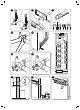
Nella modalità TURBO, il motore del ventilatore funziona a velocità molto elevata in modo da raggiungere la temperatura impostata nel minor tempo possibile. 3.4.5 - Funzione SELF CLEAN Nella modalità SELF CLEAN, il condizionatore pulisce ed asciuga automaticamente l’evaporatore e lo mantiene fresco per il successivo utilizzo. La funzione viene utilizzata allo spegnimento della modalità raffreddamento per pulire l’evaporatore e mantenerlo fresco per il successivo utilizzo.
ITALIANO 3.4.11 - Tasto LED/FOLLOW ME (11) Premere questo tasto per meno di 2 secondi per avviare la funzione LED. Se si tiene il tasto per più di 2 secondi si attiva la funzione FOLLOW ME. Premere il tasto LED per azzerare il display digitale del condizionatore; premerlo nuovamente per attivarlo. temperatura ambiente.
Il condizionatore regola automaticamente la direzione verticale dell’aria, a seconda della modalità operativa. zione desiderata. I pulsanti AIR DIRECTION e SWING saranno disabilitati quando il condizionatore non è in funzione (anche quando è impostato il TIMER ON). Non azionare il condizionatore per periodi lunghi con l’aria rivolta verso il basso nelle modalità trebbe cadere sul pavimento o sugli arredi. Non spostare le feritoie orizzontali manualmente. Utilizzare sempre il pulsante AIR DIRECTION o SWING.
ITALIANO b. Avanti Indietro direzione in cui si preme. c. Una volta settata l’ora per il TIMER ON ed il TIMER OFF, controllare che l’indicatore del TIMER sul display dell’unità interna sia acceso. MODIFICHE Dopo aver acceso l’unità, selezionare la modalità operativa, la temperatura desiderata e la velocità di ventilazione con le quali l’unità si attiverà all’accensione programmata. Successivamente mettere la macchina in Stand-By. accenderà (partendo dalla conferma del timer).
Esempio: Sono le ore 20:00. Si desidera accendere il condizionatore alle ore 6:00 del mattino successivo, e spegnerlo alle ore 8:00. a. l’orario lampeggia. b. c. l’orario lampeggia. d. e. Attendere 3 secondi, l’orario impostato smetterà di lampeggiare e la funzione sarà attiva. 3.8 - FUNZIONAMENTO MANUALE ( ) Il funzionamento manuale può essere utilizzato temporaneamente, nel caso in cui non si riesca a trovare il telecomando, oppure le sue batterie siano esaurite. a. b.
ITALIANO 4.1 - PULIZIA 4.1.1 - Pulizia dell’unità interna e del telecomando Utilizzare un panno asciutto per pulire l’unità interna e il telecomando. Il pannello frontale può essere rimosso e pulito con acqua. Asciugare quindi con un panno asciutto. Non utilizzare un panno trattato chimicamente o antistatico per pulire l’unità. Non utilizzare, benzina, solvente, pasta per lucidare, o solventi similari. in plastica. Provvedere, quindi, alla sua pulizia ogni due settimane. a. b. c. d. luogo fresco. e.
scollegata. 4.2.1 - Consigli per il risparmio energetico Di seguito alcuni semplici consigli per ridurre i consumi: Evitare che i raggi solari penetrino liberamente nell’ambiente (si consiglia l’utilizzo di tende o abbassare tapparelle o chiudere le persiane). dell’impianto non ottimale, pregiudica anche il suo corretto funzionamento e la possibilità di guasti irreparabili alle unità. 4.3 - ASPETTI FUNZIONALI DA NON INTERPRETARE COME INCONVENIENTI 1. PROTEZIONE DEL CONDIZIONATORE. a.
ITALIANO 3. LIEVE RUMORE DEL CONDIZIONATORE spento. E’ il rumore del refrigerante che scorre o si sta fermando. pena stato spento. E’ provocato dall’espansione per il calore o dalla contrazione per il freddo delle parti in plastica dell’apparecchiatura, quando la temperatura cambia. - E’ possibile avvertire un rumore dovuto al ripristino della posizione originale delle feritoie alla prima accensione. 4. VIENE SOFFIATA FUORI DELLA POLVERE DALL’UNITA’ INTERNA.
ITALIANO 4.4 - SUGGERIMENTI PER L’ELIMINAZIONE GUASTI Scollegare l’alimentazione elettrica e contattare il servizio di assistenza più vicino. - Se sul display appare uno dei seguenti codici: E0, E1, E2, E3, E5, EC, P0, P1, P2, P4, F1, F2, F3, F5, E4, F4. - I fusibili saltano di frequente o l’interruttore automatico interviene spesso. - E’ entrata dell’acqua o altri oggetti nel condizionatore. - Il telecomando non funziona o funziona in modo anomalo. 4.4.
ITALIANO 5 - DATI TECNICI Per i dati tecnici sotto elencati consultare la targa dati caratteristica applicata sul prodotto. Tensione di alimentazione Potenza assorbita massima Corrente assorbita massima Potenza refrigerante Modello Unità interna Dimensioni (mm) (Larg. x Alt. x Prof.) ............................ Peso (kg) (senza imballo) ..................
MAIN INDEX 0.1 GENERAL INFORMATION .............................................................................................................3 0.2 SYMBOLS .......................................................................................................................................3 0.2.1 - Editorial pictograms .........................................................................................................................3 0.3 GENERAL WARNINGS.............................................
ENGLISH 3.1.2 - Replacement of batteries ..............................................................................................................27 3.1.3 - Location of the remote controller ...................................................................................................28 3.2 COMPONENTS OF THE SYSTEM...............................................................................................28 3.3 FUNCTION INDICATOR ON INDOOR UNIT DISPLAY PANEL ...................................
ILLUSTRATIONS The illustrations are grouped on the initial pages of the manual MAIN INDEX Index ENGLISH The main index of this manual is given on page “EN-1” 0 - WARNINGS 0.1 - GENERAL INFORMATION First of all, we would like to thank you for choosing our appliance. transferred to third parties without the explicit authorisation of the manufacturer. The appliance may undergo updates and therefore have details different from those represented, without prejudice to the texts contained in this manual. 0.
HAZARD ENGLISH DANGER OF HIGH VOLTAGE Signals to the personnel that the operation described could cause electrocution if not performed according to the safety rules. GENERIC DANGER It informs the personnel concerned that if the operation is not carried out in compliance with the safety regulations, it presents the risk of suffering physical damage.
0.3 - GENERAL WARNINGS 1. This document is restricted in use to the terms of the law and may not be copied or transferred to third parties without the express authorization of the manufacturer, OLIMPIA SPLENDID. Our machines are subject to change and some parts may appear different from the ones shown here, without this affecting the text of the manual in any way. 2.
ENGLISH 11. Always wear gloves and protective goggles when performing any operations on the refrigerating side of the units. gasses, explosive gasses, or in very humid environments (laundries, greenhouses, etc.), or in places where there are machines that generate very great heat. 13. In case of replacement of parts, use only original OLIMPIA SPLENDID parts. 14.
23. Do not touch (operation) the product with wet hands. Fire and electric shocks risk. 24. Do not place a heater or other appliance near the power cable. Fire and electric shocks risk. 26. Do not open the air inlet grid during appliance operation. Risk of injury, electric shock or damage to the product. 27. Do not block the air inlet or outlet; the product could be damaged. 28. Do not insert hands or other object through air inlet or outlet while the product is operated.
ENGLISH 0.4 - NOTES REGARDING FLUORINATED GASES be performed at least every 12 months. highly recommended. 0.5 - PROPER USE hot or cool air (on demand) for the sole purpose of obtaining a comfortable temperature in the room. persons, property or animals relieve OLIMPIA SPLENDID of any liability. 0.6 - HAZARDOUS ZONES (laundries, greenhouses, etc.), or in places with other machines that generate a strong heat source, in proximity of a sources of salt water or sulphurous water. controller.
1 - DESCRIPTION OF THE APPLIANCE 1.1 - LIST OF THE COMPONENTS SUPPLIED The parts indicated below are included in the supply. The other items necessary for installation must be purchased. 1. Outdoor unit quantity 1 2. Indoor unit quantity from 1 to 5 (according to the model) 3. 4. Plugs 5. quantity 1 6. Gasket quantity 1 A 7. quantity 1 for each indoor unit 8. Remote control quantity 1 9. Battery for remote control quantity 2 - AAA type x 1.5V 10.
1.3 - STORAGE planks or a pallet. ENGLISH TO NOT TURN THE CARTON UPSIDE DOWN. 1.4 - RECEIPT AND UNPACKING The packaging is made up from suitable material and performed by expert personnel. The units are delivered complete and in perfect condition. However, for he quality control of the transport services, follow the warnings below: a. On receipt of the packages, check whether the packaging is damaged.
Do not install, remove, or reinstall the unit by yourself (customer). Be sure the installation area does not deteriorate with age. If the base collapses, the air conditioner could fall with it, causing property damage, product failure, and personal injury. Install the unit securely in a place which can bear the weight of the unit. --------------------------2.1.
2.1.2 - Minimum room area in the case of MID refrigerant gas load (with the mid additional load) Quantity of refrigerant gas (kg) Height of installation (m) Minimum room area (m2) DUAL 1x2 1,45 2,2 2 DUAL 1x2 1,45 1,8 2 DUAL 1x2 1,45 0,6 20 ENGLISH Model 2.1.
2.2 - CHECKS TO PERFORM BEFORE INSTALLATION a. Checks at the area b. Work procedure The job must be performed according to a controlled procedure in a way to reduce performance of the job. c. General work area All maintenance personnel and those working in the local area, must be trained regarding the job performed. Do not work in tight spaces. The area around the work area must be isolated. material. d.
ENGLISH g. Ventilated area Make sure that the area is open or suitably ventilated before interacting with the system or performing any operation at high temperatures. Ensure constant ventilation during the operations period. Ventilation must safely disperse all refrigerant released and, if possible, expel it outside into the atmosphere. h. Refrigeration system checks Always follow the manufacturer’s guide lines relative to maintenance and technical after-sales assistance.
l. Repair interventions of the hermetic components intervention on electric components, the housing is not altered in a way to affect the level of protection. This includes damage to cables, excessive number of connections, terminals not incorrect installation of the closing devices, etc. leak detection equipment. Intrinsically safe components do not have to be isolated before working on them. 2.3 - DATA TABLE 2.
DUAL INVERTER 14 DUAL INVERTER 18 1-2 1-2 Total length for all rooms max 30 m. max 30 m. Length for one indoor unit max 20 m. max 20 m. max 15 m. max 15 m. max 15 m. max 15 m. max 10 m. max 10 m. Model ENGLISH Number of units that can be used together Difference in height between the indoor and outdoor units A” ......... B” .......... Difference in height between the indoor units “C” X1 A C B h.
2.5 - INSTALLATION OF THE INSIDE UNIT 2.5.1 - Installation of fastening plate ENGLISH a. Position the plate against the wall. b. Mark the drilling points, making sure that they are level. c. Make the holes necessary in the wall using a suitable bit. Make sure there are no pipes or electric ducts in the drilling area. d e. If the wall is in wood, use relevant countersunk-head screws (not supplied). f. Check the stability of the plate (7), moving it laterally and vertically. 2.5.
For the left (C) and right (F) piping, remove the respective pipe covering (B or G) from the lateral panel. ENGLISH It is recommended to keep the pipe covering that has been removed, since it can be re-used if the air conditioner is installed in another position. Bend the connection pipe, which must be laid at a max. distance of 43 mm from the outside wall. Fix the end of the connection pipe (I). (see “Execution, installation and connection of the refrigeration lines”).
2.6 - SELECTION OF POSITION FOR OUTSIDE UNIT To obtain the best operating performance and prevent faults or hazardous conditions, the position of outdoor unit installation must meet the following requirements: d e. The outside unit must be installed perfectly level (check with a bubble level). Note: If the outdoor unit must be installed on the wall or roof, it is necessary to use the relevant kit (optional) For assembly, follow the relative instructions, attached to the kit packaging, scrupulously. f.
X3 D min. 300mm A min. 300mm min. 600mm min. 600mm ENGLISH B C min. 300mm E C min. 700mm A F mode. 2.6.2 - Outdoor unit assembly Proceed as follows (as described in the previous paragraph), once the ideal position for installation of the a b. Screw any clamping nuts, without tightening completely. c. Using a spirit level, check the unit is level; if necessary, adjust the support feet. d. Tighten any clamping nuts correctly.
2.6.3 - Execution, installation and connection of the refrigeration lines Do not make the connections using normal hydraulic piping, which could contain scrap residues, dirt or water, and which can damage the unit components and jeopardise correct operation of the appliance. When the cuts have been made, seal the end of the roll and piece cut immediately. Pre-insulated copper pipes can be used for refrigeration.
NEVER USE A NORMAL HANDSAW, scraps could fall inside the pipe and enter the circuitry of the system, damaging c. Remove possible burrs with the special tool. Immediately after cutting and deburring the pipes, seal the ends with insulating ENGLISH tape. d. If you do not use preinsulated pipes, they must be insulated as follows: 2 ) or 0.39 kcal/(h x C x m2) Do not place both pipes in the same sheath, as this would jeopardize the proper e. Bind any joints in the sheath securely with insulating tape.
h. Repeat the seal test. When all of the tests and checks regarding perfect sealing have been performed, a vacuum must be applied to the system to remove the impurities contained therein (air, nitrogen and humidity). a b. Lower the pressure inside the circuit to the absolute value of 50 Pa for approx. 2 hours. If, after this period of time, the pressure has not been taken to the set value (50 Pa), it means that there is a lot of humidity in the circuit or there is a leak. c.
installation, assistance and disposal. ENGLISH as quickly as possible. product or re-loading the gas, must be compliant with the regulations regarding 2.6.7 - Connection of the condensate drain line Connect a drain pipe, of appropriate length, to the indoor unit condensate drain pipe, and block it with a strap. Make it run inside the duct parallel to the system pipes, fastening it to the same using straps. of the pipes and narrow the drain pipe.
2.7 - ELECTRIC CONNECTIONS 2.7.1 - Electric connection between indoor and outdoor units ENGLISH The electric connection between the indoor units must have the features stated in the table of the following page. The connection cable between the outdoor unit and the indoor units must be the “H07RN-F” type. 2.7.2 - Indoor unit electric connection (Figure 29a) a. Remove the panel (21) b. Unscrew the screw and remove the protection (22). c d.
2.7.4 - Electric connection Before connecting the air conditioner, make sure that: ENGLISH plate. b. The power supply line has an effective earth connection and it is correctly dimensioned for maximum absorption of the climate control unit. c. To select the minimum section of the power supply cable, refer to the table below.
3 - USE AND MAINTENANCE 3.1 - USE OF THE REMOTE CONTROL The remote control supplied with the air-conditioner is the instrument that enables you to use the appliance in the most convenient way. ENGLISH It should be handled with care and in particular: Keep it dry (do not clean it with water or leave it outdoors in bad weather). Avoid dropping or bumping it. Keep it out of direct sunlight. The remote control operates by means of an infrared beam.
ENGLISH If the battery liquid falls onto the skin or clothes, wash well with clean water. Do not use the remote control with batteries that have leaked. The chemical products contained in the batteries can cause burns or other risks to health. 3.1.3 - Location of the remote controller Keep the remote control in a position from which the signal can reach the indoor unit receiver (max. The presence of obstacles (furniture, curtains, walls, etc.
3.3 - FUNCTION INDICATOR ON INDOOR UNIT DISPLAY PANEL K2 The display panel shows the current setting temperature and function code enable/disable when the air conditioner is in operation. ENGLISH In “Fan” and “Dehumidification” mode, the room temperature is displayed. In the case of a fault, displays the error code. 3.3.
E. Timer Indicate Timer on/off time (0÷23:50 hours). ENGLISH F. Fan speed Displays the fan speed set, AUTO and three speed levels can be indicated “ “ (LOW) - “ “ (MED) - “ “ (HIGH). “AUTO” is displayed when the operational mode is “AUTO” or “DRY”. G. Sleep Displayed under sleeping operation. Press the SLEEP button again to remove. The remote control display is illustrated just for greater clarity. 1.
3.4.4 - TURBO function In TURBO mode, the fan motor functions at a very high speed in a way to reach the temperature set in the least time possible. In SELF CLEAN mode, the air conditioner automatically cleans and dries the evaporator and keeps it fresh for successive use. The function is used on switch off of cooling mode to clean the evaporator and keep it fresh for successive use. This function is easy to activate and accessible from the remote control.
3.4.11 - LED/FOLLOW ME key (11) ENGLISH Press this key for less than 2 seconds to start the LED function. If the key is held down for more than 2 seconds, the FOLLOW ME function is activated. Press the LED key to reset the air conditioner digital display; press it again to activate it. When the air conditioner is put in “AUTO” mode, these will automatically select cooling, heating or fan, depending on the temperature that has been selected and the room temperature.
Before adjusting the vertical louvres, disconnect the electric power supply. direction. The AIR DIRECTION and SWING buttons will be disabled when the air conditioner is not operating (also when the TIMER ON is set). Do not activate the air conditioner for long periods with the air downwards in cooling or Otherwise, humidity may form on the surface of the horizontal louvres, which could fall onto the Do not move the horizontal louvres manually. Always use the AIR DIRECTION or SWING button.
ENGLISH b. Press the “TEMP” keys (4) to select the desired time. Forward Backward Every time one of the “TEMP” keys (4) is pressed, the time moves forward or backward by 30 minutes, depending on the direction of pressing. c. Once the time has been set for TIMER ON and TIMER OFF, check that the TIMER indicator on the indoor unit display is on. MODIFICATIONS Repeat phases “a”, “b” and “c” to change the settings.
(On => Stop => Start functioning) This function is useful if the air conditioner is to be switched on before getting up and switched off after leaving home. ENGLISH The time is 20:00. If the air conditioner is to be switched on at 06:00 the next morning and switched of at 08:00. a. Press the “TIMER ON” key (7) to display “TIMER ON”. b. Press the “TEMP” keys (4) until the value “10:00” is set near to the “TIMER ON” indicator. c. Press the “TIMER OFF” key (8) to display “TIMER OFF”. d.
4.1 - CLEANING 4.1.1 - Cleaning the indoor unit and remote controller Use a dry cloth to clean the indoor unit and the remote control. A cloth dampened in cold water can be used to clean the indoor unit if it is very dirty. ENGLISH The front panel can be removed and cleaned with water. Dry using a dry cloth. Do not use a chemically-treated or anti-static cloth to clean the unit. Do not use gasoline, solvent, polish or similar solvents.
There is a risk of injury due to the sharp metal edges. When cleaning the unit, make sure the switch is off and the power supply is disconnected. 4.2.1 - RECOMMENDATIONS FOR ENERGY SAVINGS Keep the doors and windows of the rooms to be climate controlled closed. Avoid the sun’s rays penetrating freely into the room (we recommend using curtains or lowering blinds or closing the shutters). affects correct operation and the possibility of irreparable faults to the units. 4.
ENGLISH 3. SLIGHT AIR CONDITIONER NOISE - A low hissing noise may be heard when the compressor is running, or has just been switched off. It is the noise of the refrigerant running or stopping. - A low “squeaking” noise may also be heard when the compressor is running, or has just been switched off. This is caused by expansion due to the heat or contraction due to cold of the plastic parts of the unit, when the temperature changes.
1. Stop the air conditioner immediately is one of the following anomalies occurs. Disconnect the electric power supply and contact the nearest after-sales assistance service. Problem: - If one of the following codes appears on the display: E0, E1, E2, E3, E5, EC, P0, P1, P2, P4, F1, F2, F3, F5, E4, F4. - The fuses blow frequently or the automatic switch intervenes often. - Water or other objects have entered the air conditioner. - The remote control does not function or functions anomalously. 4.4.
5 - TECHNICAL DATA ENGLISH Power supply voltage Maximum power absorbed Maximum current absorbed Cooling capacity Model Indoor unit Dimensions (mm) (Width x Height x Depth) .................... Weight (kg) without packaging).......... Refrigerant gas Protection rating of the casings Max.
TABLE DES MATIÈRES GÉNÉRALE 0- MISES EN GARDE........................................................................................................... 3 0.1 INFORMATIONS GÉNÉRALES ......................................................................................................3 0.2 SYMBOLOGIE ................................................................................................................................3 0.2.1 - Pictogrammes rédactionnels ............................................
FRANÇAIS 3.1.2 - Remplacement des piles ...............................................................................................................27 3.1.3 - Position de la télécommande ........................................................................................................28 3.2 COMPOSANTS DU SYSTEME ....................................................................................................28 3.3 INDICATEUR DE FONCTION SUR L’AFFICHEUR DE L’UNITE INTERNE .......................
ILLUSTRATIONS Les illustrations sont regroupées dans les pages initiales de la notice TABLE DES MATIÈRES GÉNÉRALE Index La table des matières générales de cette notice 0.1 - INFORMATIONS GÉNÉRALES Tout d’abord, nous tenons à vous remercier pour avoir décidé d’accorder votre préférence à un appareil de notre production. Document réservé aux termes de la loi avec interdiction de la reproduction ou de transmission à des tiers sans l’autorisation explicite du fabricant.
TENSION ÉLECTRIQUE DANGEREUSE Signale au personnel concerné que l’opération décrite présente, si elle n’est pas effectuée conformément aux normes de sécurité, le risque de provoquer une décharge électrique. DANGER GÉNÉRAL Il signale au personnel concerné que l’opération décrite présente, si elle n’est pas effectuée conformément aux normes de sécurité, le risque de subir des lésions physiques.
0.3 - MISES EN GARDE GÉNÉRALES 1. Document réservé aux termes de la loi avec interdiction de reproduction ou de transmission à tiers sans l’autorisation expresse de la société OLIMPIA SPLENDID. Les machines peuvent subir des mises à jour et par conséquent présenter des éléments différents de ceux qui sont représentés, sans que cela constitue pour autant un préjudice pour les textes contenus dans ce manuel. 2.
10. Exécutez les opérations d’installation et d’entretien avec un équipement adapté 11. Il faut toujours mettre des gants et chausser des lunettes de protection pour effectuer les interventions sur le côté réfrigérant des appareils. humides (buanderies, serres, etc.), ou dans des locaux où se trouvent d’autres machines produisant une importante source de chaleur. FRANÇAIS 13. En cas de remplacement de composants, utiliser exclusivement des pièces de rechange originales OLIMPIA SPLENDID. 14.
23. Ne pas toucher (s’il est en fonction) le produit avec les mains mouillées. Risque d’incendie ou de choc électrique. 24. Ne pas placer le réchauffeur ou d’autres appareils à proximité du cordon d’alimentation. Risque d’incendie ou de choc électrique. 25. Veillez à ce que l’eau n’entre pas dans les pièces électriques. Cela pourrait provoquer un incendie, une défaillance du produit ou des chocs électriques. 27.
0,4 - À PROPOS DES GAZ FLUORÉS plaque signalétique appliquée à l’unité. FRANÇAIS s’assurer de l’absence de fuites au moins tous les 12 mois. veuillez tenir un registre détaillé de toutes les inspections consignées. 0.5 - UTILISATION PRÉVUE froid (au choix) dans le seul but de rendre agréable la température ambiante. dommages causés aux personnes, aux biens ou aux animaux dégage la société OLIMPIA SPLENDID de toute responsabilité. 0.6 - ZONES À RISQUE serres, etc.
1 - DESCRIPTION DE L’APPAREIL 1.1 - LISTE DES COMPOSANTS FOURNIS Les unités composant le système de climatisation sont conditionnées individuellement dans un emballage en carton. Il est possible de transporter les emballages, pour des unités simples, à la main par deux personnes préposées, ou chargés sur un chariot transporteur même empilés pour un maximum de trois emballages, étant donné qu’il s’agit d’une unité intérieure, ou individuellement pour l’unité extérieure.
1.3 - STOCKAGE Stocker les caisses dans un local fermé et protégé des agents atmosphériques, isolées du sol par des traverses ou des palettes. NE PAS RENVERSER L’EMBALLAGE. 1.4 - RÉCEPTION ET DÉBALLAGE FRANÇAIS L’emballage est réalisé en matériau approprié et exécuté par un personnel expert. observez les mises en garde ci-dessous : a marchandises avec cautèle, et rassemblez des preuves photographiques des dommages apparents, si nécessaire. b c.
Le client ne doit pas installer, enlever ou réinstaller l’appareil par lui-même. Il y a risque d’incendie, d’électrocution, d’explosion ou de blessure. Pour l’installation, contacter toujours le revendeur ou un centre d’assistance agréé. Il y a risque d’incendie, d’électrocution, d’explosion ou de blessure. Installer dans un point robuste et solide, en mesure de supporter le poids. Ne pas installer l’appareil dans un lieu où il pourrait y avoir des fuites de gaz --------------------------2.1.
2.1.2 - Quantité de gaz réfrigérant (kg) Hauteur d’installation (m) Zone ambiante minimale (m2) DUAL 1x2 1,45 2,2 2 DUAL 1x2 1,45 1,8 2 DUAL 1x2 1,45 0,6 20 Modèle Quantité de gaz réfrigérant (kg) Hauteur d’installation (m) Zone ambiante minimale (m2) DUAL 1x2 1,60 2,2 4 DUAL 1x2 1,60 1,8 4 DUAL 1x2 1,60 0,6 25 FRANÇAIS Modèle 2.1.
2.2 - CONTRÔLES À EFFECTUER AVANT L’INSTALLATION A. Contrôles de la zone Avant de commencer à travailler sur des systèmes contenant des liquides réfrigérants d’ignition. Pour réparer un système de réfrigération, il est nécessaire de respecter les consignes suivantes avant de travailler sur le système. c. Zone de travail générale Tout le personnel d’entretien et ceux qui travaillent dans la zone locale doivent être formés sur la nature du travail effectué. Évitez de travailler dans des espaces exigus.
g. Zone ventilée Assurez-vous que la zone est ouverte ou qu’elle est correctement ventilée avant d’interagir avec le système ou d’effectuer toute opération à haute température. Assurez une ventilation constante pendant la période de fonctionnement. La ventilation doit disperser en toute sécurité tout réfrigérant dégagé et, si possible, l’expulser vers l’extérieur dans l’atmosphère. FRANÇAIS Suivez toujours les lignes directrices du fabricant concernant l’entretien et l’assistance technique.
l. Opérations de réparation des composants hermétiques d’alimentation électrique doivent être déconnectées de l’appareil avant le retrait éventuel des capots étanches à l’air, etc. S’il est absolument nécessaire d’avoir une alimentation électrique pour l’équipement pendant l’entretien, il est nécessaire de prévoir un détecteur de fuite constamment actif au point le plus critique pour signaler une situation potentiellement dangereuse. le niveau de protection.
DUAL INVERTER 14 DUAL INVERTER 18 1-2 1-2 Longueur totale pour toutes les pièces max 30 m. max 30 m. Longueur pour une unité intérieure max 20 m. max 20 m. max 15 m. max 15 m. max 15 m. max 15 m. max 10 m. max 10 m. Modèle Nombre d’unités pouvant être combinées FRANÇAIS Différence de hauteur entre les unités intérieures et extérieures A B Différence de hauteur entre les unités intérieures C X1 A C B h.
2.5 - MONTAGE DE L’UNITE INTERIEURE a. Placez la plaque contre la paroi. b. Marquez les points de forage en vous assurant qu’ils sont à niveau. c. Faites les trous nécessaires avec une pointe appropriée pour la paroi à percer. Assurez-vous qu’il n’y a pas de tubes ou de conduits électriques dans la zone de perçage. FRANÇAIS d e. Si la paroi est en bois, utilisez des vis à tête fraisée appropriées (non fournies). f 2.5.
Pour les tuyauteries gauche (C) et droite (F), retirez le capot des tubes correspondant (B ou G) du panneau latéral. Nous vous recommandons de garder le capot des tubes retiré car il pourrait être réutilisé si vous FRANÇAIS Pliez le tube de raccordement à poser à une distance maximale de 43 mm de la paroi extérieure.
2.6 - CHOIX DE LA POSITION DE L’UNITÉ EXTÉRIEURE la position d’installation de l’unité extérieure doit répondre aux exigences suivantes : a b. Elle doit être à l’abri des agents atmosphériques (pluie, neige) et des courants directs des vents violents c. Elle doit être située à l’abri d’éventuelles aspersions abondantes d’eau (arrosages, écoulements de gouttières) d e f. L’unité ne doit pas être en mesure d’entraver le passage des personnes ou des animaux. g.
X3 D min. 300mm A min. 300mm min. 600mm min. 600mm B C min. 300mm E C min. 700mm A FRANÇAIS F en mode chauffage. 2.6.2 - Montage de l’unité extérieure précédent), procédez comme suit : a. Positionnez l’unité sur la base de support en respectant les distances du centre de forage indiquées dans b c d IN = entrée d’air - OUT = sortie d’air IN F1 X4 IN OUT F2 Modèle DUAL INVERTER 14 1x2 DUAL INVERTER 18 1x2 “F1” 340 340 “F2” 514 514 e.
2.6.3 - Exécution, pose et raccordement des lignes de réfrigération pouvant contenir des résidus de copeaux, de saleté ou de l’eau, et susceptibles d’endommager les composants des unités et compromettre le bon fonctionnement de l’équipement. fournis propres et scellés aux extrémités. FRANÇAIS Après avoir fait les coupes, scellez immédiatement les extrémités du rouleau et le bout coupé. Il est possible d’utiliser des tubes en cuivre pré-isolés pour la réfrigération.
NE JAMAIS UTILISER UNE SCIE NORMALE, les copeaux pourraient entrer dans le tuyau et par la suite entrer en circulation c. Enlever les bavures éventuelles à l’aide d’un outil approprié. du tuyau avec du ruban isolant. d. Si l’on n’utilise pas de tuyauterie préisolée, introduire les tuyaux dans l’isolant qui doit avoir les caractéristiques suivantes: FRANÇAIS 2 ) soit 0.39 kcal/(h x C x m2) Ne pas introduire les deux tuyaux dans la même gaine, cela compromet le fonce.
avec les panneaux correspondants. h. Répéter ensuite les essais d’étanchéité. Une fois que tous les essais et les contrôles ont été effectués parfaitement, il est nécessaire de mettre le système sous vide pour nettoyer les impuretés qu’il contient (air, azote et humidité). a b. Faites baisser la pression à l’intérieur du circuit jusqu’à la valeur absolue de 50 Pa pendant environ 2 heures. c. Gardez la pompe en marche pendant encore 3 heures pour le vide.
- l’installation, l’assistance ou l’élimination. FRANÇAIS possible. tation locale en vigueur en la matière. 2.6.7 - Raccordement de la ligne de vidange des condensats Reliez au tube d’évacuation des condensats de l’unité interne un tube de drainage de la longueur appropriée Acheminez-le dans la conduite parallèlement aux tubes du système, en les arrêtant avec des colliers de serrage.
2.7 - BRANCHEMENTS ÉLECTRIQUES 2.7.1 - Branchement électrique entre les unités intérieures et l’unité extérieure le tableau de la page suivante. H07RN-F 2.7.2 - Branchement électrique de l’unité interne (Figure 29a) FRANÇAIS a. Retirez le panneau (21) b. Dévissez la vis, puis retirez la protection (22). c d aucun composant électrique. e 21 Panneau 22 Couvercle du bornier 23 Bornier d’unité intérieure 24 25 2.7.3 - Branchement électrique de l’unité externe (Figure 29b) a.
2.7.4 - Branchement électrique Avant de relier le climatiseur, assurez-vous que : dimensionnée pour une absorption maximale du climatiseur. c Nombre de pôles du câble d’alimentation Section minimale du câble d’alimentation Fusible recommandé DUAL 1x2 3 1,5 mm2 12 A FRANÇAIS Modèle d’unité externe Un dispositif de déconnexion omnipolaire approprié doit être prévu sur le réseau d’alimentation de l’appareil conformément aux règles d’installation nationales.
3 - MODE D’EMPLOI ET ENTRETIEN 3.1 - MODE D’EMPLOI DE LA TELECOMMANDE La télécommande qui accompagne le climatiseur est l’instrument qui vous permet une utilisation plus pratique de l’appareillage. Lors de son utilisation ne pas interposer d’obstacles entre la télécommande et le climatiseur. télécommande et le climatiseur. Retirer les piles d’alimentation en cas de non utilisation prolongée de la télécommande. 3.1.
Elles peuvent brûler ou exploser. Si le liquide des piles tombe sur la peau ou les vêtements, lavez soigneusement sentent des fuites. d’autres risques pour la santé. FRANÇAIS 3.1.3 - Position de la télécommande Tenez la télécommande dans une position à partir de laquelle le signal peut atteindre le récepteur de l’unité intérieure (distance maximale d’environ 8 mètres - avec les piles chargées) (Figure 32). La présence d’obstacles (meubles, rideaux, murs, etc.
3.3 - INDICATEUR DE FONCTION SUR L’AFFICHEUR DE L’UNITE INTERNE K2 paramétrée et le code de fonction activée/désactivée lorsque le climatiseur est en marche. la température ambiante. FRANÇAIS 3.3.1 - Codes Fonction Il reste allumé pendant 3 secondes lorsque : - TIMER ON est paramétré, - les fonctions SWING, TURBO ou SILENCE sont activées. Il reste allumé pendant 3 secondes lorsque : - TIMER OFF est paramétré, - les fonctions SWING, TURBO ou SILENCE sont désactivées.
E. Timer Indique l’heure d’allumage et d’extinction du temporisateur (0÷23:50). F. Vitesse du ventilateur “ (LOW) - “ AUTO “ (MED) - “ “ (HIGH). AUTO DRY G. Sleep FRANÇAIS Appuyer sur le bouton SLEEP pour annuler la fonction. 1. Bouton de SÉLECTION DE MODE Chaque fois que ce bouton est pressé, un mode séquence est sélectionné, AUTO > COOL DRY > HEAT > FAN et retour à AUTO. 2. Bouton de marche/arrêt ON/OFF Appuyez sur ce bouton pour démarrer le fonctionnement de l’appareil.
3.4.4 - Fonction TURBO En mode SELF CLEAN, le climatiseur nettoie et sèche automatiquement l’évaporateur et le maintien au frais pour une utilisation ultérieure. Cette fonction est utilisée lorsque le mode de refroidissement est désactivé pour nettoyer l’évaporateur et le garder au frais pour une utilisation ultérieure. Cette fonction est facile à activer et accessible depuis la télécommande.
3.4.11 - Bouton LED / FOLLOW ME (11) Appuyez sur ce bouton pendant moins de 2 secondes pour démarrer la fonction LED. Maintenez le bouton enfoncé pendant plus de 2 secondes pour activer la fonction FOLLOW ME. 3.4.12 - Fonctionnement automatique (Figure 34) FRANÇAIS chauffage ou la ventilation, en fonction de la température sélectionnée et de la température ambiante.
Le climatiseur règle automatiquement la direction verticale de l’air, en fonction du mode de fonctionnement. Effectuez cette fonction pendant que l’appareil fonctionne. vers la direction souhaitée. les meubles. Utilisez toujours le bouton AIR DIRECTION ou SWING. Si elles sont orientées manuellement, une défaillance risque de survenir. En cas de défaillance au niveau des fentes, arrêtez le climatiseur et redémarrez-le. C’est le fonctionnement normal. 3.6- DÉSHUMIDIFICATION ( ) START a. b. c.
b. Avance Recul minutes, selon la direction dans laquelle vous appuyez. c. de l’unité intérieure est allumé. FRANÇAIS CHANGEMENTS Après avoir allumé l’appareil, sélectionnez le mode de fonctionnement, la température souhaitée et la vitesse du ventilateur avec laquelle l’unité sera activé à l’allumage programmé. Ensuite, mettez la machine en veille. Si vous n’appuyez sur aucun bouton dans les 5 secondes qui suivent, la fonction de réglage du minuteur s’arrête automatiquement.
(On => Stop => Start fonctionnement) Cette fonction est utile si vous voulez allumer le climatiseur avant de vous lever et que vous voulez l’éteindre après avoir quitté la maison. Exemple : Il est 20h00. Vous souhaitez allumer le climatiseur à 6h00 le lendemain matin et l’éteindre à 8h00. a. l’heure clignote. b. c. l’heure clignote. d. 3.8 - FONCTIONNEMENT MANUEL ( FRANÇAIS e. Attendez 3 secondes, le délai paramétré cessera de clignoter et la fonction sera active.
4.1 - NETTOYAGE Utilisez un chiffon sec pour nettoyer l’unité intérieure et la télécommande. Le panneau avant peut être retiré et nettoyé à l’eau. Ensuite, séchez avec un chiffon sec. reil. FRANÇAIS Ces produits peuvent entraîner la rupture ou la déformation de la surface en plastique. de procéder à son nettoyage toutes les deux semaines. a. b. puis le tirer vers le bas c. d. e. de la grille d’entrée. Il y a risque d’électrocution. f. deux heures. g. h. i. 4.2 - ENTRETIEN a.
N’utilisez pas d’eau pour nettoyer les parties internes du climatiseur. Lors du nettoyage de l’unité, assurez-vous que l’interrupteur est éteint et que 4.2.1 - CONSEILS POUR L’ECONOMIE D’ENERGIE Gardez les portes et les fenêtres des pièces à climatiser fermées. Évitez que les rayons du soleil pénètrent librement dans l’environnement (nous vous recommandons d’utiliser des rideaux ou des stores ou de fermer les volets).
3. LÉGER BRUIT DU CLIMATISEUR C’est le bruit du liquide réfrigérant qui coule ou s’arrête. ou qu’il vient d’être éteint. Il est causé par la dilatation thermique ou la contraction à froid des pièces en plastique de l’équipement lorsque la température change. - Il est possible d’entendre un bruit dû au retour à la position d’origine des fentes au premier allumage. FRANÇAIS 4. DE LA POUSSIÈRE EST SOUFFLÉE DE LA POUSSIÈRE À PARTIR DE L’UNITÉ INTÉRIEURE.
4.4 - SUGGESTIONS DE DÉPANNAGE 1. Arrêtez immédiatement le climatiseur si l’un des défauts suivants se produit. Débranchez l’alimentation et contactez le service après-vente le plus proche. Problème : - Si l’un des codes suivants apparaît à l’écran : E0, E1, E2, E3, E5, EC, P0, P1, P2, P4, F1, F2, F3, F5, E4, F4. - Les fusibles grillent fréquemment ou le disjoncteur se déclenche souvent. - De l’eau ou d’autres objets sont entrés dans le climatiseur. - La télécommande ne fonctionne pas ou est défaillant. 4.
5 - DONNÉES TECHNIQUES appliquée au produit. Puissance réfrigérante Gaz réfrigérant Degré de protection des enveloppe Pression maximale de fonctionnement Tension d’alimentation Puissance maximale absorbée Consommation de courant maximale FRANÇAIS Modèle Unité intérieure Dimensions (mm) (Larg. x Alt. X Prof.)............................ Poids (kg) (sans emballage) ..............
ALLGEMEINES INHALTSVERZEICHNIS 0 - HINWEISE .................................................................................................................................. 3 0.1 ALLGEMEINE HINWEISE...............................................................................................................3 0.2 BILDSYMBOLE ...............................................................................................................................3 0.2.1 - Bildsymbole ..................................
DEUTSCH 3.1.2 - Austausch der Batterien ................................................................................................................27 3.1.3 - Position der Fernbedienung ..........................................................................................................28 3.2 SYSTEMKOMPONENTEN ...........................................................................................................28 3.3 FUNKTIONSANZEIGEN AUF DEM DISPLAY DER INNENEINHEIT .........................
ILLUSTRATIONEN Die Illustrationen sind auf den Anfangsseiten des Handbuchs zusammengefasst ALLGEMEINES INHALTSVERZEICHNIS Inhaltsverzeichn is Das allgemeine Inhaltsverzeichnis des Handbuchs 0.1 - ALLGEMEINE HINWEISE Wir möchten uns zunächst dafür bedanken, dass Sie sich für ein Gerät unserer Herstellung entschieden haben. Es handelt sich um ein gesetzlich vertrauliches Dokument, dessen Vervielfältigung und Weitergabe an Dritte ohne ausdrückliche Genehmigung des Herstellers verboten ist.
GEFÄHRLICHE ELEKTRISCHE SPANNUNG Zeigt dem betreffenden Personal an, dass bei der beschriebenen Tätigkeit die Gefahr eines elektrischen Schlags besteht, wenn diese nicht unter Beachtung der Sicherheitsvorschriften durchgeführt wird. ALLGEMEINE GEFAHR Weist das betroffene Personal darauf hin, dass der beschriebene Vorgang das Risiko für körperliche Schäden (Verletzungsgefahr) birgt, wenn er entgegen der Sicherheitsvorschriften ausgeführt wird.
0.3 - ALLGEMEINE HINWEISE BEIM UMGANG MIT ELEKTROGERÄTEN MÜSSEN STETS GEWISSE GRUNDLEGENDE SICHERHEITSMASSNAHMEN BEACHTET WERDEN, UM DIE GEFAHR VON BRAND, STROMSCHLÄGEN UND VERLETZUNGEN ZU REDUZIEREN, DARUNTER: 1. Laut Gesetz ist dies ein vertrauliches Dokument, daher gilt das Verbot der Vervielfältigung oder Übermittlung an Dritte ohne ausdrückliche Genehmigung der Firma OLIMPIA SPLENDID. An den Geräten können technische Neuerungen vorgenommen werden, d.h. Einzelteile können u.U.
10. Bei den Installations- und Wartungsmaßnahmen für brennbares Gas angemessene Ausrüstung verwenden. 11. Bei Eingriffen an der Kühlseite der Geräte sind stets Schutzhandschuhe und Schutzbrille zu tragen. 12. Die Klimaanlagen DÜRFEN NICHT in Räumen installiert werden, in denen Feuchtigkeit herrscht (Wäschereien, Gewächshäuser usw.) oder in Räumen, 13. Bei der Auswechslung von Einzelteilen bitte ausschließlich original OLIMPIA SPLENDID-Ersatzteile verwenden. DEUTSCH 14.
23. Berühren Sie (falls in Betrieb) das Produkt nicht mit feuchten Händen. Brand- oder Stromschlaggefahr. 24. Positionieren Sie die Heizung oder andere Geräte nicht in der Nähe des Versorgungskabels. Brand- oder Stromschlaggefahr. 25. Darauf achten, dass das Wasser nicht in die Elektrobauteile eindringt. Es kann Brände, Produktschäden oder Stromschläge hervorrufen. 26. Das Lufteintrittsgitter nicht öffnen, solange das Gerät in Betrieb ist. Verletzungs- und Stromschlaggefahr, Gefahr von Produktschäden. 27.
0.4 - ANMERKUNGEN ZU FLUORIERTEN GASEN Typenschild am Gerät. Fachmann vorzunehmen. Abwesenheit von Leckagen mindestens alle 12 Monate zu überprüfen. zu registrieren. DEUTSCH 0.5 - BESTIMMUNGS-GEMÄSSE VERWENDUNG (nach Wahl) verwendet werden, damit in den Räumlichkeiten eine angenehme Temperatur geschaffen wird. beschriebene Verwendung hinausgeht, gilt als nicht zulässig und enthebt die Fa. OLIMPIA SPLENDID von jeder Verantwortung. 0.
1 - BESCHREIBUNG DES GERÄTS 1.1 - AUFSTELLUNG DER BEILIEGENDEN KOMPONENTEN Die Einheiten, aus denen sich das Klimagerät zusammensetzt, werden einzelnen in Kartons verpackt. Die Verpackungen können bei einzelnen Geräten von zwei Personen von Hand transportiert werden. Zum Transport mit einem Hubwagen können bei der Inneneinheit bis zu drei Verpackungen gestapelt werden, die Außeneinheit ist einzeln zu befördern.
1.3 - LAGERUNG auf Paletten oder entsprechenden Untersätzen aufzubewahren. DIE KARTONS DÜRFEN NICHT AUF DEN KOPF GESTELLT WERDEN. 1.4 - EMPFANG UND AUSPACKEN Das Gerät wird von Fachleuten sachgemäß mit geeigneten Materialien verpackt. Die Geräte werden vollständig und in perfektem Zustand geliefert, dennoch ist zur Überprüfung der Qualität der Transportdienste Folgendes zu beachten: a. Ist der Verpackung bei Empfang der Ware beschädigt, nehmen Sie die Sendung unter Vorbehalt an und b.
Das Gerät darf nicht selbst (Kunde) installiert, entfernt oder neu installiert werden. Es besteht die Gefahr von Stromschlägen, Explosionen und Verletzungen. Nehmen Sie für die korrekte Installation stets Kontakt mit dem Händler oder einem autorisierten Kundendienstzentrum auf. Es besteht die Gefahr von Stromschlägen, Explosionen und Verletzungen. Stellen Sie sicher, dass der Installationsbereich langfristig unbeschädigt bleibt.
2.1.2 - Mind. Umgebungsbereich bei MITTLERER Ladung von Kältegas (mit mittlerer Zusatzladung) Kältemittelmenge (kg) Montagehöhe: (m) Mind. Umgebungsbereich (m2) 1,45 2,2 2 1,45 1,8 2 1,45 0,6 20 DEUTSCH Modell 2.1.3 - Mind. Umgebungsbereich bei MAXIMALER Ladung von Kältegas (mit maximaler Zusatzladung) Modell DE - 12 Kältemittelmenge (kg) Montagehöhe: (m) Mind.
2.2 - VORAB-ÜBERPRÜFUNGEN (VOR DER INSTALLATION) a. Überprüfung der Fläche Vor der Durchführung von Arbeiten an Anlagen mit brennbaren Kältemitteln sind gewisse Sicherheitskontrollen zur Minimierung der Brandgefahr erforderlich. Vor der Reparatur von Kühlanlagen müssen folgende Vorsichtsmaßnahmen berücksichtigt werden. b. Vorgehensweise Die Arbeiten sind nach einer kontrollierten Vorgehensweise auszuführen, um das Risiko von vorhandenem brennbarem Gas oder Dampf während der Arbeit zu minimieren. d.
g. Belüfteter Bereich Vor Arbeiten an der Anlage oder Eingriffen bei hohen Temperaturen sicherstellen, dass der Bereich offen und angemessen belüftet ist. Während des Vorgangs für eine konstante Belüftung sorgen. Die Belüftung muss freigesetztes Kältemittel sicher verteilen und nach Möglichkeit nach außen in die Atmosphäre ableiten. h.
l. Reparaturmaßnahmen der hermetischen Komponenten Versorgungsleitungen vom Gerät getrennt sein, bevor etwaige hermetische Verschlüsse entfernt werden. Ist die hergestellte elektrische Versorgung der Geräte während der Wartung unbedingt erforderlich, so muss an der kritischsten Stelle ein laufend aktives Kältemittelmessgerät aufgestellt werden, um eine etwaige gefährliche Situation rechtzeitig anzuzeigen.
Modell Anzahl der kombinierbaren Geräte Gesamtlänge für alle Räume Länge pro Innengerät DUAL INVERTER 14 DUAL INVERTER 18 1-2 1-2 max 30 m. max 30 m. max 20 m. max 20 m. max 15 m. max 15 m. max 15 m. max 15 m. max 10 m. max 10 m. Höhenunterschied zwischen den Innen- und Außengeräten A B Höhenunterschied zwischen den Innengeräten C DEUTSCH X1 A C B h. Das Innengerät darf nicht direkt über Haushaltsgeräten (Fernseher, Radio, Kühlschrank, usw.
2.5 - MONTAGE DER INNENEINHEIT 2.5.1 - Montage der Befestigungs-platte der Montage der Montageplatte fort (7), beachten Sie dazu die Abmessungen in Abbildung X2. a. Die Platte an der Wand positionieren. b. Die Bohrpunkte markieren und die korrekte Nivellierung der Platte sicherstellen. c. Die erforderlichen Bohrungen mit einer geeigneten Bohrspitze ausführen. Sicherstellen, dass im Bohrbereich keine Rohre oder Stromleitungen verlaufen. d.
2.5.3 - Anschluss der Leitungen (Abbildung 7) Für die linken (C) und rechten (F) Leitungen muss der entsprechende Leitungsverschluss (B oder G) von der seitlichen Abdeckung abgenommen werden. Die Leitungsverschlüsse nach Möglichkeit aufbewahren, damit sie bei Änderungen des Installationsorts des Klimageräts wiederverwendet werden können. Für die hinteren rechten (E) und linken (D) Leitungen die Rohre wie in Abbildung 7 dargestellt installieren.
2.6 - POSITIONIERUNG DER AUSSENEINHEIT Für eine optimale Geräteleistung und zur Vermeidung von Defekten oder Gefahrensituationen muss die Installationsposition des Außengeräts folgende Anforderungen erfüllen: a. Die Einheit ist gegen Sonneneinstrahlung geschützt zu montieren (Abb. 11). b montieren (Abb. 11). c. Die Einheit ist gegen Tropfwasser (aus Blumenvasen, Regenrinnen) geschützt zu montieren (Abb. 12). d. Die Tragplatte muss dem Gewicht der Außeneinheit standhalten (Abb. 12). e.
X3 D min. 300mm A min. 300mm min. 600mm min. 600mm B C min. 300mm E C min. 700mm A F Eine weitere Option (Abbildung 16) ist die Anbringung der Dichtung (6) am Verbindungsstück (5), um dieses dann in die Bohrung an der Unterseite des Außengeräts zu verlegen und sie um 90° zu drehen, DEUTSCH An das Verbindungsstück (6) eine (nicht im Lieferumfang enthaltene) Schlauchleitung anschließen, falls das Wasser im Heizbetrieb vom Außengerät abgeleitet wird. 2.6.
2.6.3 - Aufstellen, Verlegen und Anschluss der Kühlleitungen Für die Anschlüsse keine normalen Wasserleitungen verwenden, die möglicherweise Rückstände von Spänen, Schmutz oder Wasser im Inneren aufweisen und somit die Komponenten der Geräte beschädigen und deren korrekten Betrieb beeinträchtigen können. Verwenden Sie ausschließlich spezielle Kühlleitungen aus Kupfer, die sauber und an den Enden versiegelt geliefert werden.
AUF KEINEN FALL DARF EINE NORMALE SÄGE VERWENDET WERDEN, da die Späne sowohl in das Rohr als auch in den Kreislauf der Anlage eindringen und die Komponenten ernsthaft beschädigen könnten (Abb. 19a). c. Das Rohr eventuell entgraten. Nach dem Zuschnitt und der Entgratung des Rohrs sind dessen Enden mit Isolierband zu versiegeln. d. Kommen keine vorisolierten Rohrleitungen zur Anwendung, sind diese mit einem Isolierstoff zu ummanteln, der die folgenden Merkmale aufweisen muss: 2 ) oder 0.
Anschlussstellen der Leitungen auftreten. Die Muttern ggf. noch fester ziehen (Abbildung 23) oder die Anschlüsse zunächst aufkelchen und dann erneut ausführen. h. Die Dichtigkeitsprüfungen wiederholen. 2.6.5 - Anlagenvakuum Nach sämtliche Kontrollen und Dichtheitsprüfungen vorgenommen wurden, muss in der Anlage ein Vakuum erzeugt werden, um etwaige Unreinheiten (Luft, Stickstoff, Feuchtigkeit) rückstandslos zu entfernen. a.
am Einfüllpunkt angebrachte Etikett kleben. oder bei der Entsorgung nicht in die Atmosphäre freigesetzt wird. schnellstmöglich behoben werden. Der Kundenservice an diesem Produkt ist AUSSCHLIESSLICH Fachpersonal vorbehalten. mit dem Produkt oder beim Nachfüllen des Gasers, hat in Übereinstimmung mit DEUTSCH etwaigen anwendbaren, lokalen Normen zu erfolgen. und mit einer Rohrschelle verriegeln. Dann wird es in der Rinne parallel zu den Anlagenrohren verlegt und mit Schellen an diesen befestigt.
2.7 - ELEKTRISCHE ANSCHLÜSSE 2.7.1 - Stromanschluss zwischen Innen- und Außengerät Das Stromanschlusskabel zwischen den Inneneinheiten muss die in der Tabelle auf nächster Seite genannten Merkmale aufweisen. H07RN-F 2.7.2 - Stromanschluss des Innengeräts (Abbildung 29a) a. b. c. d. Abdeckung (21) abnehmen Die Schraube lösen und den Schutz (22) entfernen. Die Kabel an die Klemmleiste (23) wie in den Abbildungen 50 und 51 dargestellt anschließen.
2.7.4 - Stromanschluss Vor dem Anschluss des Klimageräts sicherstellen, dass: a. die Spannungs- und Frequenzwerte der Versorgung den Angaben auf dem Typenschild des Geräts entsprechen. Klimageräts korrekt dimensioniert ist. c. Zur Wahl des Mindestquerschnitts des Versorgungskabels siehe unten stehende Tabelle.
3 - BEDIENUNG UND WARTUNG 3.1 - BENUTZUNG DER FERNBEDIENUNG Mit der mit dem Klimagerät mitgelieferten Fernbedienung können Sie das Gerät bequem bedienen. Gehen Sie bitte sehr sorgfältig mit der Fernbedienung um, insbesondere: sollte sie nicht nass gemacht werden (nicht mit Wasser reinigen oder in den Regen legen). darf sie nicht fallen gelassen werden oder heftige Stöße erleiden. darf sie nicht direkter Sonneneinstrahlung ausgesetzt werden. Die Fernbedienung arbeitet mit Infrarot-Technologie.
Feuer werfen. Sie können Feuer fangen oder explodieren. gründlich abgewaschen werden. Die Fernbedienung nicht mit Batterien benutzen, an denen bereits Leckagen aufgetreten sind. Die in den Batterien enthaltenen Chemikalien können Verbrennungen oder andere Gesundheitsrisiken hervorrufen. 3.1.3 - Position der Fernbedienung Die Fernbedienung in einer Position halten, aus der das Signal den Empfänger des Innengeräts erreicht (max. Abstand ca. 8 Meter - bei vollen Batterien) (Abbildung 32).
3.3 - FUNKTIONSANZEIGEN AUF DEM DISPLAY DER INNENEINHEIT (Abb. K2) K2 Das digitale Display zeigt die aktuell eingestellte Temperatur und den aktivierte/deaktivierten Funktionscode an, wenn das Klimagerät in Betrieb ist. die Raumtemperatur angezeigt. Im Störungsfall wird der Fehlercode angezeigt. 3.3.
E. Timer F. Geschwindigkeit des Lüfters Zeigt die eingestellte Geschwindigkeit des Lüfters an, AUTO sowie drei Geschwindigkeitsstufen AUTO DRY AUTO G. Sleep Erscheint während des Betriebs im Modus Sleep. Drücken Sie den Taster SLEEP zum Abschalten der Funktion. 3.4.2 - Beschreibung der Tasten der Fernbedienung (Abbildung 34) 1. Taste AUSWAHL BETRIEBSMODUS AUTO > COOL DRY > HEAT > FAN und dann wieder AUTO. DEUTSCH 2.
3.4.4 - Funktion TURBO Im Betriebsmodus TURBO läuft der Motor des Lüfters bei deutlich erhöhter Geschwindigkeit, um die eingestellte Temperatur in möglichst kurzer Zeit zu erreichen. 3.4.5 - Funktion SELF CLEAN Diese Funktion ist nur im Betriebsmodus COOL (AUTO COOL, FORCED COOL) und DRY verfügbar. Vor der Auswahl dieser Funktion sollte das Klimagerät ca. eine halbe Stunde im Kühlbetrieb laufen. Nach der Aktivierung der Auto Clean Funktion werden sämtliche Timer Einstellungen gelöscht.
3.4.11 - Taste LED/FOLLOW ME (11) Diese Taste weniger als 2 Sekunden drücken, um die LED Funktion zu starten. Diese Taste mindestens 2 Sekunden lang drücken, um die FOLLOW ME Funktion zu starten. Die Taste LED drücken, um das digitale Display des Klimageräts nullzustellen; erneut drücken, um es zu aktivieren. 3.4.12 - Automatikbetrieb (Abbildung 34) Lüftungsbetrieb aus, abhängig von der eingestellten Temperatur und der Raumtemperatur.
Vor der Einstellung der vertikalen Schlitze muss die Stromversorgung getrennt werden. 3.5.1 - Einstellung der vertikalen Strömungsrichtung der Luft (hoch - tief) (Abbildung “36”) Diese Funktion ausführen, wenn das Gerät in Betrieb ist. gewünschte Richtung zu verstellen. die sich auf den Boden und die Einrichtung niederschlagen kann. Die horizontalen Schlitze nicht manuell verstellen. Verwenden Sie dazu stets die Taste AIR DIRECTION oder SWING. Bei manueller Verstellung kann es zu Betriebsstörungen kommen.
b. Vor Zurück dem, in welcher Richtung gedrückt wird. c. Nach der Einstellung der TIMER ON und TIMER OFF Zeit kontrollieren, dass die TIMER Anzeige auf dem Display des Innengeräts leuchtet. ÄNDERUNGEN 3.7.1 - Einstellung des Einschalt-Timers über die Fernbedienung (Abbildungen 33, 34 und 37) Nach dem Einschalten des Geräts den Betriebsmodus auswählen, die gewünschte Temperatur und Geschwindigkeit des Lüfters, mit denen das Gerät beim programmierten Einschalten laufen soll.
TIMER ON > TIMER OFF (Abbildungen “33”, “34” und “40”) (On => Stop => Betriebsstart) Diese Funktion ist nützlich, wenn das Klimagerät vor dem Aufstehen eingeschaltet und beim Verlassen des Hauses abgeschaltet werden soll. Beispiel: Es ist 20.00 Uhr. Das Klimagerät soll um 06.00 Uhr morgens eingeschaltet und um 08.00 Uhr wieder ausgeschaltet werden. a. Die Uhrzeit blinkt. b. c. Die Uhrzeit blinkt. d. e. 3 Sekunden warten, bis die eingestellte Uhrzeit zu blinken aufhört und die Funktion aktiviert ist. 3.
4.1 - REINIGUNG 4.1.1 - Reinigung der Inneneinheit und der Fernbedienung Zur Reinigung der Fernbedienung und des Innengerät einen trockenen Lappen verwenden. Man kann auch einen mit kaltem Wasser angefeuchteten Lappen zur Reinigung des Innengeräts verwenden, wenn dieses stark verschmutzt ist. Die vordere Klappe kann entfernt und mit Wasser abgewaschen werden. Dann mit einem trockenen Lappen nachtrocknen. Zur Reinigung des Geräts keine chemische behandelten oder antistatischen Lappen verwenden.
Beim Herausnehmen des Filters die Metallteile des Geräts nicht berühren. Verletzungsgefahr durch scharfe Kanten. Zur Reinigung der Innenteile des Klimageräts kein Wasser verwenden. Wasser kann die Isolierung beschädigen und somit eine erhöhte Stromschlaggefahr bewirken. Bei der Reinigung des Geräts stets darauf achten, dass der Schalter abgeschaltet und die Stromversorgung getrennt ist. 4.2.1 - TIPPS ZUM ENERGIESPAREN 4.
3. LEICHTE GERÄUSCHE DES KLIMAGERÄTS - Wenn der Kompressor läuft oder gerade ausgeschaltet wurde kann man ein leises Säuseln hören. Es ist das Geräusch des Materials, das durch das Gerät strömt oder zum Stehen kommt. ausgeschaltet wurde. Das hängt von der wärmebedingten Ausdehnung oder kältebedingten Kontraktion der Kunststoffbestandteile ab, wenn sich die Temperatur ändert. - Bei der Wiederherstellung der ursprünglichen Position der Schlitze beim ersten Anlaufen ist eine Geräuschbildung möglich. 4.
4.4 - TROUBLE SHOOTING 1. Das Klimagerät bei Eintreten einer der folgenden Störungen sofort stoppen. Trennen Sie die Stromversorgung und wenden Sie sich an das nächste Servicezentrum. Problem: - Auf dem Display erscheint einer der folgenden Codes: E0, E1, E2, E3, E5, EC, P0, P1, P2, P4, F1, F2, F3, F5, E4, F4. - Eindringen von Wasser oder anderen Gegenständen in das Klimagerät. - Die Fernbedienung funktioniert nicht oder nicht richtig. 4.4.
5 - TECHNISCHE DATEN Versorgungsspannung Max. Leistungsaufnahme Max. Stromaufnahme Modell Kältegas Schutzart der Gehäuse Max. Betriebsdruck DUAL INVERTER 14 DUAL INVERTER 18 36 36 Innengerät Abmessungen (mm) (Breite x Höhe x Tiefe) ....................... Gewicht (kg) (unverpackt) ..................
ÍNDICE GENERAL 0- ADVERTENCIAS ............................................................................................................. 3 0.1 INFORMACIONES GENERALES ...................................................................................................3 0.2 SIMBOLOGÍA ..................................................................................................................................3 0.2.1 - Pictogramas informativos ..........................................................
3.1.2 - Substitución de las pilas ................................................................................................................27 3.1.3 - Posición del control remoto ...........................................................................................................28 3.2 COMPONENTES DEL SISTEMA..................................................................................................28 3.3 INDICADOR DE FUNCIÓN EN EL DISPLAY DE LA UNIDAD INTERNA .............................
ILUSTRACIONES Las ilustraciones están agrupas en las páginas iniciales del manual. ÍNDICE GENERAL Índice El índice general de este manual se proporciona en la página “ES-1”. 0 - ADVERTENCIAS 0.1 - INFORMACIONES GENERALES En primer lugar, deseamos darle las gracias por haber elegido uno de nuestros aparatos. Documento reservado en conformidad con la ley con prohibición de reproducción y transmisión a terceros sin autorización explícita del fabricante.
TENSIÓN ELÉCTRICA PELIGROSA Señala al personal interesado que la operación descripta presenta, si no es realizada respetando las normativas de seguridad, el riesgo de sufrir un shock eléctrico. PELIGRO GENÉRICO Señala al personal implicado que, si la operación descrita no se realiza respetando las normas de seguridad, existe el riesgo de sufrir daños físicos.
0.3 - ADVERTENCIAS GENERALES CUANDO SE UTILIZAN APARATOS ELÉCTRICOS, PARA REDUCIR EL RIESGO DE INCENDIO, DE DESCARGAS ELÉCTRICAS Y DE PROVOCAR DAÑOS A PERSONAS, ES NECESARIO TOMAR SIEMPRE LAS MEDIDAS DE SEGURIDAD ADECUADAS Y TENER EN CUENTA LOS SIGUIENTES CONSEJOS: 1. Documento reservado según la ley con prohibición de reproducción o transmisión a terceros sin la expresa autorización de la empresa OLIMPIA SPLENDID.
10. Efectúe las operaciones de instalación y mantenimiento utilizando equipos 11. Es necesario llevar puestos guantes y gafas de protección para realizar intervenciones en la parte refrigerante de los equipos. 12. Los climatizadores NO DEBEN ser instalados en ambientes con presencia de invernaderos, etc.), o en locales donde se encuentren otras maquinarias que generen una fuerte fuente de calor. 13. En caso de substitución de componentes utilizar exclusivamente repuestos originales OLIMPIA SPLENDID. 14.
23. No toque el aparato con las manos mojadas cuando está en funcionamiento. Riesgo de incendio o descargas eléctricas. 24. No coloque el calentador u otros aparatos cerca del cable de alimentación. Riesgo de incendio o descargas eléctricas. 25. Preste atención a que el agua no entre en contacto con partes eléctricas. Riesgo de incendio, averías del aparato o descargas eléctricas. 26. No abra la rejilla de entrada de aire cuando el aparato esté funcionando.
0.4 - NOTAS SOBRE LOS GASES FLUORADOS la placa de datos aplicada en la unidad. es necesario controlar que no haya pérdidas al menos cada 12 meses. registro detallado con todas las inspecciones. 0.5 - USO PREVISTO caliente o frío (a elección) con el único objetivo de hacer que la temperatura en el ambiente sea confortable. ESPAÑOL daños causados en personas, cosas o animales libran a la empresa OLIMPIA SPLENDID de toda responsabilidad. 0.
1 - DESCRIPCIÓN DEL APARATO 1.1 - LISTA DE COMPONENTES SUMINISTRADOS DE SERIE Las unidades que componen el sistema de climatización se embalan por separado en embalajes de cartón. Los embalajes de cartón con las unidades individuales pueden ser transportados a mano por dos personas o bien pueden cargarse en una carretilla de transporte, apilados hasta un máximo de tres si trata de unidades interiores o bien individualmente si se trata de la unidad exterior.
1.3 - ALMACENAMIENTO Almacenar los paquetes en un ambiente cerrado y protegido de los agentes atmosféricos, aislados del suelo mediante pequeñas traviesas o pallets. NO VOLCAR EL EMBALAJE. 1.4 - RECEPCIÓN Y DESEMBALAJE El embalaje está constituido por material adecuado y realizado por personal experto. Las unidades se entregan completas y en perfectas condiciones; sin embargo, para comprobar que no se hayan dañado durante el transporte, le aconsejamos que tenga en cuenta las siguientes advertencias: a.
No instale, quite ni reinstale el aparato por su cuenta (cliente). Para la instalación, contacte siempre con el revendedor o con un centro de asistencia autorizado. Si la base cae, también podría caer el acondicionador, provocando daños a --------------------------2.1.
2.1.2 - ESPAÑOL (con la media carga adicional) Modelo Cantidad de gas refrigerante (kg) Altura de instalación (m) Área de la habitación mínima (m2) DUAL 1x2 1,45 2,2 2 DUAL 1x2 1,45 1,8 2 DUAL 1x2 1,45 0,6 20 2.1.
2.2 - CONTROLES QUE SE DEBEN EFECTUAR ANTES DE LA INSTALACIÓN a. Controles en el área necesario efectuar controles de seguridad para reducir al mínimo el riesgo de ignición. Para reparar una instalación de refrigeración, hay que respetar siempre las siguientes precauciones. b. Procedimiento de trabajo Trabaje siempre según un procedimiento controlado, adecuado para reducir al mínimo c.
g. Área ventilada Asegúrese de que el área esté abierta o debidamente ventilada antes de trabajar en la instalación o realizar cualquier operación a altas temperaturas. Asegure una ventilación constante mientras se realizan las operaciones. La ventilación debe eliminar de forma segura el refrigerante liberado y, si es posible, expulsarlo al exterior. h. Controles en la instalación de refrigeración Siempre hay que seguir las directrices del fabricante sobre el mantenimiento y la asistencia técnica.
l. Intervenciones de reparación de los componentes herméticos las líneas de alimentación eléctrica tienen que desconectarse del aparato en funcionamiento antes de quitar las coberturas herméticas, etc. Si es absolutamente necesario disponer de alimentación eléctrica para los aparatos durante el mantenimiento, se debe colocar un detector de pérdidas siempre activo en el punto más crítico para señalar cualquier situación potencialmente peligrosa.
DUAL INVERTER 14 DUAL INVERTER 18 1-2 1-2 Longitud total para todas las habitaciones max 30 m. max 30 m. Longitud para una unidad interior max 20 m. max 20 m. max 15 m. max 15 m. max 15 m. max 15 m. max 10 m. max 10 m. Modelo Número de unidades que se pueden combinar Diferencia de altura entre las unidades interiores y la unidad exterior A” B” Diferencia de altura entre las unidades interiores “C” 1 ESPAÑOL A C B h.
2.5 - MONTAJE DE LA UNIDAD INTERNA 2.5.1 - Montaje de la placa de sujeción Después de comprobar que se cumplan las condiciones descritas en el apartado “2.2” y en la página anterior a. Coloque la placa contra la pared. b. Marque los puntos de taladrado asegurándose de que la placa esté nivelada. c cas. d e. Si la pared es de madera, utilice tornillos de cabeza avellanada (no suministrados). f. Compruebe la estabilidad de la placa (7) desplazándola lateral y verticalmente.
Para las tuberías izquierda (C) y derecha (F), quite las protecciones de los tubos (B o G) del panel lateral. Se aconseja guardar las protecciones de los tubos ya que podrían ser necesarias en caso de colocar el acondicionador en otro sitio. Doble el tubo de conexión, que debe tenderse a una distancia máxima de 43 mm de la pared externa.
2.6 Para obtener el mejor rendimiento de funcionamiento y evitar averías o situaciones de peligro, la posición de instalación de la unidad exterior debe cumplir con los requisitos siguientes: a b. Tiene que estar protegida de los agentes atmosféricos (lluvia, nieve) y de las corrientes directas de vientos c. Tiene que encontrarse en una posición protegida de eventuales vuelcos copiosos de agua (regaderas, d e.
3 D min. 300mm A min. 300mm min. 600mm min. 600mm B C min. 300mm E C min. 700mm A F Conecte al racor (6) un tubo de goma (no suministrado) en caso de que el agua se drene desde la unidad exterior en modo calefacción. 2.6.2 - Montaje de la unidad exterior ESPAÑOL Después de localizar la posición ideal para instalar la unidad exterior (como se ha descrito en el apartado anterior), proceda de la siguiente manera: a b c.
los componentes de la unidad y perjudicar el correcto funcionamiento de los aparatos. ministran limpias y selladas en los extremos. Tras realizar los cortes, selle inmediatamente los extremos del rollo y del trozo de tubo cortado. Es posible utilizar tubos de cobre para refrigeración ya preaislados. Utilice exclusivamente tubos con los diámetros indicados en el apartado “Datos técnicos”.
NO UTILIZAR NUNCA UN SERRUCHO NORMAL, las virutas podrían entrar en el tubo y sucesivamente podrían circular por la insc. Quitar eventuales rebabas con la herramienta apropiada. Apenas realizado el corte y quitadas las rebabas cerrar las extremidades del tubo con cinta aislante. d. En caso que no sean utilizadas tuberías preaisladas, colocar los tubos en el aislante que debe tener las siguientes características: 2 ) o bien 0.
los empalmes con los correspondientes avellanados. h. Luego repetir nuevamente las pruebas de hermeticidad. 2.6.5 - Puesta en vacío de la instalación Una vez terminadas todas las pruebas y comprobaciones para asegurarse de que la instalación es perfectamente hermética, es necesario llevar a cabo la puesta en vacío para eliminar las impurezas contenidas en la instalación (aire, nitrógeno y humedad). a.
operaciones de instalación, asistencia o eliminación. lo antes posible. La asistencia para este producto SOLO está permitida a personal altamente cua- el desplazamiento manual del producto o la recarga de gas) debe ser conforme eventuales normas locales aplicables. 2.6.7 - Conexión de la línea de descarga de la condensación Conecte un tubo de drenaje de longitud adecuada al tubo de descarga de la condensación de la unidad interior y bloquéelo con una abrazadera.
2.7 2.7.1 - Conexión eléctrica entre las unidades interiores y la unidad exterior El cable de conexión eléctrica entre las unidades interiores debe tener las características indicadas en la tabla de la página siguiente. El cable de conexión entre las unidades interiores y la unidad exterior debe ser tipo “H07RN-F”. a. Quite el panel (21) b. Desenrosque el tornillo y quite la protección (22). c d.
2.7.4 - Conexión eléctrica Antes de conectar el climatizador, asegúrese de que: aparato. dimensionada para el máximo consumo del aparato. c. Para determinar la sección mínima del cable de alimentación, consulte la tabla siguiente.
3 - USO Y MANTENIMIENTO 3.1 - USO DEL MANDO A DISTANCIA El mando a distancia entregado con el equipamiento base del climatizador es el instrumento que permite utilizar el equipamiento de una manera más cómoda. Es el instrumento que hay que manejar con cuidado y particularmente hay que: Evitar mojarlo (no hay que limpiarlo con agua o dejarlo a la intemperie). Evitar que se caiga al suelo o se golpee violentamente. Evitar la exposición directa a los rayos solares.
No recargue ni desarme las baterías. No arroje las baterías al fuego. Pueden quemarse o explotar. Si el líquido de las baterías cae sobre la piel o la ropa, lave con abundante agua Los productos químicos de las baterías pueden provocar quemaduras u otros riesgos para la salud. 3.1.3 - Posición del control remoto Mantenga el mando a distancia en una posición desde la cual la señal pueda alcanzar el receptor de la La presencia de obstáculos (muebles, cortinas, paredes, etc.
3.3 - INDICADOR DE FUNCIÓN EN EL DISPLAY DE LA UNIDAD INTERNA 2 rada y el código de función activada/desactivada, cuando el acondicionador está en funcionamiento. la temperatura ambiente. En caso de avería, visualiza el código de error. 3.3.1 - CÓDIGOS DE FUNCIÓN Iluminado durante 3 segundos cuando: - las funciones SWING, TURBO o SILENCE están habilitadas. Iluminado durante 3 segundos cuando: - las funciones SWING, TURBO o SILENCE están inhabilitadas.
E. Timer F. Velocidad del ventilador velocidad: “ “ (LOW) - “ “ (MED) - “ “ (HIGH). Se visualiza la palabra “AUTO” cuando el modo operativo es “AUTO” o “DRY”. G. Sleep Se visualiza durante el funcionamiento en modo SLEEP. Pulse el botón SLEEP para anular la función. La pantalla del mando a distancia solo se ilustra para una mayor claridad. 1. Botón MODE Cada vez que se pulsa este botón, se selecciona un modo de funcionamiento con el siguiente orden: AUTO > COOL DRY > HEAT > FAN y retorno a AUTO. 2.
3.4.4 - Función TURBO En el modo TURBO, el motor del ventilador funciona a velocidad muy elevada para alcanzar la temperatura 3.4.5 - Función SELF CLEAN En modo SELF CLEAN, el acondicionador limpia y seca automáticamente el evaporador y lo mantiene a punto para cuando vuelva a usarse. para el siguiente uso. Es fácil de activar y accesible desde el mando a distancia. El acondicionador funcionará de la siguiente manera: - Modo solo ventilación con el ventilador a baja velocidad (13 minutos).
3.4.11 - Botón LED/FOLLOW ME (11) Pulse este botón durante menos de 2 segundos para activar la función LED. Si este botón se mantiene pulsado durante más de 2 segundos, se activa la función FOLLOW ME. Pulse el botón LED para poner a cero la pantalla digital del acondicionador; púlselo de nuevo para activarla.
Antes de regular las ranuras verticales, desconecte la alimentación eléctrica. El acondicionador regula automáticamente la dirección vertical del aire según el modo operativo seleccionado. Realice esta operación con la unidad en funcionamiento. la dirección deseada. por períodos prolongados. caer sobre el suelo o sobre los muebles. Utilice siempre los botones AIR DIRECTION o SWING. Si se orientan manualmente, se puede producir un mal funcionamiento.
b. Pulse los botones “TEMP” (4) para seleccionar el horario deseado. Adelante Atrás Cada vez que se pulsa uno de los botones “TEMP” (4), el horario se adelanta o retrocede 30 minutos, según la dirección en la que se pulsa. c. pantalla de la unidad interior esté encendido. MODIFICACIONES Repita las fases “a”, “b” y “c” para cambiar las regulaciones.
(On => Stop => Start funcionamiento) Esta función es útil si se desea activar el acondicionador antes de levantarse y se desea apagarlo después de salir de casa. Ejemplo: Son las 20:00 horas. Si se desea encender el acondicionador a las 6:00 horas de la mañana siguiente y apagarlo a las 8:00 horas. a. Pulse el botón “TIMER ON” (7) para visualizar en la pantalla “TIMER ON”; el horario parpadea. b. Pulse los botones “TEMP” (4) hasta visualizar “10:00” cerca del indicador “TIMER ON”. c.
4.1 - LIMPIEZA 4.1.1 - Limpieza de la unidad interior y del control remoto Utilice un paño seco para limpiar la unidad interior y el mando a distancia. Es posible utilizar un paño humedecido con agua fría para limpiar la unidad interior si está muy sucia. Es posible quitar el panel frontal y limpiarlo con agua. Luego, séquelo con un paño seco. No utilice un paño tratado químicamente o antiestático para limpiar la unidad. No utilice gasolina, solventes, pastas para limpiar ni solventes similares. plástico.
No utilice agua para limpiar las partes interiores del acondicionador. La exposición al agua puede deteriorar el aislamiento, con riesgo de provocar descargas eléctricas. Al limpiar la unidad, compruebe que el interruptor esté apagado y la alimentación desconectada. 4.2.1 - CONSEJOS PARA EL AHORRO DE ENERGÍA A continuación se proporcionan algunos simples consejos para reducir los consumos: Mantenga cerradas las puertas y ventanas de las habitaciones que se deben climatizar.
3. LEVE RUIDO DEL ACONDICIONADOR - Es posible oír un ligero silbido cuando el compresor está funcionando o recién ha sido apagado. Es el ruido del refrigerante que circula o se está deteniendo. - Es posible oír un ligero chirrido cuando el compresor está funcionando o recién ha sido apagado. Es provocado por la expansión o la contracción de los componentes de plástico del aparato, debida a los cambios de temperatura.
4.4 - SUGERENCIAS PARA LA REPARACIÓN DE AVERÍAS 1. Apague inmediatamente el acondicionador si se produce una de las siguientes anomalías. Desconecte la alimentación eléctrica y contacte con el servicio de asistencia más cercano. Problema: - Si en la pantalla se visualiza uno de los siguientes códigos: E0, E1, E2, E3, E5, EC, P0, P1, P2, P4, F1, F2, F3, F5, E4 o F4. - Los fusibles saltan a menudo o el interruptor automático interviene con frecuencia. - Ha entrado agua u otros objetos en el acondicionador.
5 - DATOS TÉCNICOS Para los datos técnicos enumerados a continuación, consulte la placa de datos aplicada en el producto. Tensión de alimentación Potencia absorbida máxima Corriente absorbida máxima Potencia refrigerante Modelo Unidad interior Dimensiones (mm) (Ancho x Alto x Prof.) ......................... Peso (kg) (sin embalaje) ....................
ÍNDICE GERAL 0 - ADVERTÊNCIAS........................................................................................................................ 3 0.1 INFORMAÇÕES GERAIS ...............................................................................................................3 0.2 SIMBOLOGIA ..................................................................................................................................3 0.2.1 - Pictogramas redaccionais ............................................
..................................................................................................................27 ...............................................................................................................28 3.2 COMPONENTES DO SISTEMA ...................................................................................................28 3.3 INDICADOR DE FUNÇÃO NO DISPLAY DA UNIDADE INTERNA ..............................................29 .................................................
ILUSTRAÇÕES ÍNDICE GERAL Índice O índice geral do presente manual está indicado na página “PT-1” 0 - ADVERTÊNCIAS 0.1 - INFORMAÇÕES GERAIS Em primeiro lugar, gostaríamos de agradecer-lhe por manifestado a sua preferência por 0.2 - SIMBOLOGIA Os pictogramas ilustrados no presente capítulo fornecem rapidamente e de modo unívoco 0.2.1 - Pictogramas redaccionais PORTOGUÊS Service SERVIÇO DE ASSISTÊNCIA TÉCNICA AOS CLIENTES.
TENSÃO ELÉTRICA PERIGOSA PERIGO GENÉRICO PERIGO DE FORTE CALOR com elevada temperatura. NÃO COBRIR ATENÇÃO ou utilizar o aparelho.
0.3 - ADVERTÊNCIAS GERAIS QUANDO SE USAM APARELHOS ELÉTRICOS, É SEMPRE NECESSÁRIO SEGUIR MEDIDAS DE SEGURANÇA DE BASE, DE FORMA A REDUZIR RISCOS DE INCÊNDIO, CHOQUE ELÉTRICO E ACIDENTES A PESSOAS, INCLUINDO O SEGUINTE: 1. Documento reservado nos termos da Lei que proíbe a reprodução ou a SPLENDID. As máquinas poderão sofrer actualizações e apresentar pormenores diferentes daqueles ilustrados, mas que não prejudicam o conteúdo dos textos presentes neste manual. 2.
10. Realizar as operações de instalação e manutenção usando equipamentos de intervenção no lado refrigerante dos aparelhos. 12. Os climatizadores NÃO DEVEM ser instalados em ambientes com presença (lavandarias, estufas, etc.), ou em locais onde existam outras máquinas que geram uma forte fonte de calor. 13. Em caso de substituição de componentes utilizar exclusivamente peças de substituição originais OLIMPIA SPLENDID. 14.
23. Não tocar (se estiver a funcionar) o aparelho com as mãos molhadas. Risco de incêndio ou choque elétrico. 24. Não colocar o aquecedor ou outras aparelhagens junto ao cabo de alimentação. Risco de incêndio ou choque elétrico. 25. Prestar atenção para que a água não entre nas partes elétricas. Poderá provocar incêndios, avarias no aparelho ou choque elétrico. 26. Não abrir a grelha de entrada de ar durante o funcionamento do aparelho. 27. 28.
0.4 - NOTA SOBRE OS GASES FLUORADOS consultar a placa de dados aplicada na unidade. necessário controlar a ausência de fugas pelo menos a cada 12 meses. recomenda-se que mantenha um registo detalhado de todas as inspeções. 0.5 - USO PREVISTO escolha) com o único objectivo de tornar confortável a temperatura do ambiente. causados a pessoas, coisas ou animais livram a OLIMPIA SPLENDID de toda a responsabilidade. 0.
1 - DESCRIÇÃO DO APARELHO 1.1 - LISTA DE COMPONENTES FORNECIDOS COM O APARELHO carregadas num carro transportador até um máximo de três embalagens, tratando-se da unidade interna, ou individualmente para a unidade externa. As partes indicadas de seguida estão incluídas no fornecimento, as outras peças necessárias para a instalação deverão ser adquiridas à parte. 7. 1. Unidade externa quantidade 1 2. Unidade interna quantidade de 1 a 5 (segundo o modelo) 3. 4. Buchas 5. quantidade 1 6.
1.3 - ARMAZENAGEM Armazenar as embalagens num ambiente fechado e protegido contra os agentes atmosféricos, isolando-as NÃO VIRAR EMBALAGEM AO CONTRÁRIO. 1.4 - RECEÇÃO E DESEMBALAMENTO A embalagem é constituída por material adequado e realizado por pessoal especializado. a com cuidado, fotografando os eventuais danos aparentes. b c d e às abas do condensador e evaporador. e OLIMPIA SPLENDID. Nenhuma informação relativa a danos sofridos poderá ser tomada para análise após 3 dias desde a entrega.
Não instalar, retirar ou reinstalar o aparelho sozinho (cliente). Existe o perigo de incêndio ou de choques eléctricos, explosão ou ferimentos. Para a instalação, contactar sempre o Revendedor ou um Centro de Assistência autorizado. Existe o perigo de incêndio ou de choques eléctricos, explosão ou ferimentos. veis. --------------------------2.1.
2.1.2 (com média carga adicional) Modelo Quantidade de gás refrigerante (kg) Altura de instalação (m) Área ambiente mínima (m2) DUAL 1x2 1,45 2,2 2 DUAL 1x2 1,45 1,8 2 DUAL 1x2 1,45 0,6 20 2.1.
2.2 - CONTROLOS A EFETUAR ANTES DA INSTALAÇÃO a. Controlos na área antes de trabalhar no sistema. b. Procedimento de trabalho O trabalho é executado através de um procedimento controlado de forma a reduzir ao c. Área de trabalho geral pela natureza do trabalho desenvolvido. d. Controlo da presença de refrigerante ou intrinsecamente segura. e. Presença de extintores PORTOGUÊS nos respetivos componentes, é necessário preparar um sistema anti-incêndio adequado. carregamento. f.
g. Área ventilada possível, expulsá-lo externamente para a atmosfera. h. Controlos no sistema de refrigeração controlos. PORTOGUÊS protegidos contra agentes corrosivos. i. Controlos nos dispositivos elétricos todas as partes.
l. Intervenções de reparação dos componentes herméticos potencialmente perigosa. de aparelhos para a deteção de fugas. PORTOGUÊS 2.3 - TABELA DE DADOS 2.4 - ESCOLHA DA POSIÇÃO DA UNIDADE INTERNA a b c. A unidade interna deve ser instalada a uma altura de um mínimo de 2 metros e máximo de 3 metros do d o seu peso. e. f.
Modelo Número unidades a combinar Comprimento total para todas as Comprimento para uma unidade interna DUAL INVERTER 14 DUAL INVERTER 18 1-2 1-2 max 30 m. max 30 m. max 20 m. max 20 m. max 15 m. max 15 m. max 15 m. max 15 m. max 10 m. max 10 m. internas e externa A” ....... .......
2.5 - MONTAGEM DA UNIDADE INTERNA a. Posicionar a placa contra a parede. b c d e f 2.5.2 - Realização dos furos para passagem dos tubos “R” para a passagem dos tubos, a R b.
Para as tubagens esquerda (C) e direita (F), remover a respetiva cobertura dos tubos (B ou G) do painel lateral. condicionador tiver de ser instalado noutra posição. A Porta-tubo B C Tubagem esquerda D Tubagem posterior esquerda E Tubagem posterior direita F Tubagem direita G H Saída unidade interna I L Gancho superior M Gancho inferior N Material de enchimento a. Engatar o suporte superior presente na parte posterior da unidade interna ao gancho superior do suporte b.
2.6 - ESCOLHA DA POSIÇÃO DA UNIDADE EXTERNA a b. Deve estar reparada dos agentes atmosféricos (chuva, neve) e das correntes directas dos ventos fortes c d e Nota: Caso a unidade externa tenha de ser instalada na parede ou teto, é necessário usar o kit respetivo (opcional). f g h i problema. l m interior da unidade e provocar danos aos componentes elétricos. PORTOGUÊS n. Posicionamento da unidade num plano de área útil (varanda, terreno, telhado, etc.) em zonas de difícil acesso.
X3 D min. 300mm A min. 300mm min. 600mm min. 600mm B C min. 300mm E C min. 700mm A F no modo de aquecimento. 2.6.2 - Montagem da unidade externa a b c aos pés de apoio. d IN = entrada de ar - OUT = saída de ar PORTOGUÊS IN F1 X4 IN OUT F2 Modelo DUAL INVERTER 14 1x2 DUAL INVERTER 18 1x2 “F1” 340 340 “F2” 514 514 e. Se a unidade externa for mais alta do que as unidades internas, para evitar que a chuva chegue ao exterior.
2.6.3 - Execução, colocação e ligações das linhas de refrigeração componentes das unidades e prejudicar o correto funcionamento dos aparelhos. fornecidas limpas e seladas nas extremidades. Depois de ter realizado os cortes, selar imediatamente as extremidades do rolo e da secção cortada. para obter o máximo rendimento do sistema. permitido. Para estabelecer se é necessário rebocar a carga de gás, consultar a tabela abaixo.
NUNCA UTILIZAR UM SERROTE NORMAL, c. Remover eventuais rebarbas com uma ferramenta apropriada. d. Caso se utilizem tubagens pré-isoladas, introduzir os tubos no isolante que deverá ter as seguintes ca- 2 2 ) e f g. Lixar as extremidades do tubo, utilizando uma ferramenta apropriada, de modo impecável, sem roturas, h NÃO UTILIZAR NENHUM OUTRO TIPO DE LUBRIFICANTE. i.
respetivas brasagens. h. Repetir a prova de estanqueidade. 2.6.5 - Sistema em vácuo vácuo do sistema para uma limpeza das impurezas nele contidas (ar, azoto e humidade). a b c procura da fuga. d remover a conexão da bomba quando esta ainda estiver em funcionamento. e 2.6.6 - Enchimento do sistema Abrir o capacete de fecho para poder atuar na torneira permitem o enchimento do refrigerante no aparelho. plaque proximidade do ponto de carga e/ou reposição.
colá-la em cima da que estava anteriormente colada no ponto de carga. instalação, assistência ou eliminação. durante a deslocação manual do produto ou recarga do gás, deve estar em conforaplicáveis. 2.6.7 - Ligação da linha de descarga da condensação adequado e bloqueá-lo com uma cinta. Deslizá-lo dentro do canal de modo paralelo com os tubos do sistema, parando-o com estas cintas. PORTOGUÊS águas brancas.
2.7 - LIGAÇÕES ELÉCTRICAS 2.7.1 - Ligação elétrica entre as unidades internas e unidade externa página seguinte. H07RN-F”. 2.7.2 - Ligação elétrica entre as unidades internas (Figura 29a) a. Remover o painel (21) b c d nenhum componente elétrico. e. Bloquear o cabo (28) com o gancho para cabos (29). 21 22 23 24 25 Painel Tampa da placa de terminais Placa de terminais da unidade interna Gancho para cabos 2.7.3 - Ligação elétrica da unidade externa (Figura 29b) a b das unidades interna e externa.
2.7.4 - Ligação elétrica do aparelho. dimensionada para a máxima absorção do climatizador. c Modelo Unidade Externa Número polos cabo de alimentação Secção mínima do cabo de alimentação elétrica Fusível recomendado DUAL 1x2 3 1,5 mm2 12 A Na rede de alimentação elétrica do aparelho deve estar previsto um adequado dispositivo de ligação omnipolar em conformidade com as regras de instalação nacionais. ou curto-circuitos.
3 - USO E MANUTENÇÃO 3.1 - USO DO TELECOMANDO instrumento que vos permite de utilizar o aparelho de maneira mais cómoda. intempéries). O telecomando funciona com a tecnologia a infra-vermelhos. telecomando e o climatizador. 3.1.1 - Introdução das pilhas a. Retirar a tampa do compartimento das pilhas. b. Inserir as pilhas no respetivo compartimento. Respeitar escrupulosamente as polaridades indicadas no fundo do vão. PORTOGUÊS c. Fechar corretamente o compartimento. 3.1.
Não recarregar ou desmontar as pilhas. Não deitar as pilhas no fogo. Podem arder ou explodir. com água limpa. Não usar o comando com pilhas que tenham tido fugas. riscos para a saúde. 3.1.3 - Posição do telecomando o alcance do comando. 3.
3.3 - INDICADOR DE FUNÇÃO NO DISPLAY DA UNIDADE INTERNA 2 cionador está em funcionamento. temperatura ambiente. Em caso de avaria, visualiza o código de erro. 3.3.1 - CÓDIGOS FUNÇÃO 3.4 - DESCRIÇÃO DO TELECOMANDO O telecomando é a interface entre o utilizador e o climatizador e é muito importante aprender a conhecer A. Transmission B. Modo de funcionamento Visualiza o modo de funcionamento ativo. AUTO , COOL , DRY , HEAT C. , FAN ONLY e regresso a AUTO . Follow me D.
E. Timer F. Velocidade do ventilador “ É visualizado “AUTO “ (MED) - “ “ (HIGH). AUTO” ou “DRY”. G. Sleep É visualizado durante o funcionamento em modalidade SLEEP. O visor do comando é ilustrado apenas para uma maior clareza. 1. Botão SELEÇÃO DE MODO AUTO > COOL DRY > HEAT > FAN depois regressa a AUTO. 2. Botão ON/OFF funcionamento. 3. Botão SWING funcionamento. 4. Botão TEMP/TIME sentido horário. PORTOGUÊS 5. Botão FAN 6. Botão TURBO/SELF CLEAN 3.4.3 - Função Follow me Follow Me Me”.
3.4.4 - Função TURBO 3.4.5 - Função SELF CLEAN No modo SELF CLEAN, o condicionador limpa e seca automaticamente o evaporador e mantém-no - Aquecimento com o ventilador a baixa velocidade (1 minuto) - Paragem de funcionamento - Desligamento da unidade. Antes de selecionar esta função, é recomendável iniciar o condicionador em modo de arrefecimento durante cerca de meia-hora. a função para e o aparelho desliga-se. 3.4.6 - Função SILENCE PORTOGUÊS 3.4.7 - Função FP 3.4.
3.4.11 - Botão LED/FOLLOW ME (11) Quando o condicionador é colocado em modo “AUTO”, este selecionará automaticamente o arrefecimento, o START a. b. Normalmente, a temperatura encontra-se entre 21°C e 28°C. c. STOP a. do ventilador é controlada automaticamente. PORTOGUÊS START a. b. Normalmente, a temperatura encontra-se entre 21°C e 28°C. c. d. e. executar apenas as fases “a”, “c”, “d”, “e”. STOP a. 3.5 - REGULAÇÃO DA DIRECÇÃO DO AR temperaturas irregulares no ambiente. a.
Antes de regular as grelhas verticais, desligar a alimentação elétrica. no chão ou nos móveis. Não deslocar as grelhas horizontais manualmente. Quando o condicionador é ligado logo após ter sido desligado, as grelhas horizontais podem demasiado apertado. Não acionar o aparelho com as grelhas horizontais na posição fechada. Quando o condicionador for ligado à alimentação (alimentação inicial), as grelhas horizontais 3.6- DESUMIDIFICAÇÃO ( ) PORTOGUÊS START a. b. c. STOP a. 3.
b. Recuar c. da unidade interna está ligado. ALTERAÇÕES Depois, colocar em máquina em standby. automaticamente. PORTOGUÊS automaticamente. O visor do comando visualiza a contagem decrescente para o desligamento. Exemplo: a. b. c. d. e.
de sair de casa. Exemplo: a. b. c. d. e. 3.8 - FUNCIONAMENTO MANUAL ( ) a. b. c. AUTO > COOL > OFF. Este modo deve ser usado apenas para efeitos de teste. 4 - MANUTENÇÃO E LIMPEZA se sempre de ter desligado o sistema através do comando, e de ter desligado a PT - 35 ARYAL S1 E PORTOGUÊS Para repor o funcionamento a partir do comando, usar diretamente o comando.
4.1 - LIMPEZA 4.1.1 - Limpeza da unidade interna e do telecomando Usar um pano seco para limpar a unidade interna e o comando. O painel frontal pode ser removido e limpo com água. Secar com um pano seco. Não usar um pano tratado quimicamente ou antistático para limpar a unidade. Portanto, efectuar a sua limpeza cada duas semanas. a. b. - c. d. e. entrada. Existe o risco de choque eléctrico. f. g. originalmente). PORTOGUÊS h. i. 4.2 - MANUTENÇÃO a.
Não usar água para limpar as peças internas do condicionador. A exposição à água pode estragar o isolamento, com o risco de provocar choque elétrico. alimentação desligada. 4.2.1 - CONSELHOS PARA POUPAR ENERGIA Evitar que os raios solares penetrem livremente no ambiente (recomenda-se o uso de cortinas ou baixar as persianas ou estores). 4.3 - ASPECTOS DE FUNCIONAMENTO A NÃO CONSIDERAR COMO PROBLEMAS 1. PROTEÇÃO DO CONDICIONADOR a. - Aquecimento a baixa temperatura. b.
3. LIGEIRO RUÍDO DO CONDICIONADOR - É possível sentir um ligeiro sibilo quando o compressor estiver a funcionar ou acabou de ser desligado. É o ruído do refrigerante que escorre ou está a parar. - É também possível sentir um ligeiro chiar quando o compressor estiver a funcionar ou acabou de plástico do aparelho quando a temperatura muda. se liga. 4. SAI PÓ DA UNIDADE INTERNA. - É uma coisa normal quando o condicionador é reiniciado após um longo período de inatividade, ou pela primeira vez. 5.
4.4 - SUGESTÕES PARA A ELIMINAÇÃO DE AVARIAS Problema: E0, E1, E2, E3, E5, EC, P0, P1, P2, P4, F1, F2, F3, F5, E4, F4. - Os fusíveis soltam-se frequentemente ou o interruptor automático intervém muitas vezes. 4.4.1 - Avarias Não tentar reparar o aparelho sozinho. Avaria Causa O que é preciso fazer? O aparelho não arranca resposta. A unidade desligou-se da corrente. Disparou um fusível. Substituir o fusível. As pilhas do comando podem estar Substituir as pilhas. gastas. do temporizador.
5 - DADOS TÉCNICOS Gás refrigerante Potência absorvida máxima Corrente absorvida máxima Potência refrigerante DUAL INVERTER 14 1x2 DUAL INVERTER 18 1x2 (Larg. x Alt. x Prof.) ............................ 800 x 554 x 333 800 x 554 x 333 Peso (kg) (sem embalagem)..............
INHOUDSOPGAVE 0- WAARSCHUWINGEN ...................................................................................................... 3 0.1 ALGEMENE INFORMATIE .............................................................................................................3 0.2 SYMBOLEN ....................................................................................................................................3 0.2.1 - Redactionele pictogrammen..........................................................
3.1.2 - Vervanging van de batterijen .........................................................................................................27 3.1.3 - Positie van de afstandsbediening..................................................................................................28 3.2 COMPONENTEN VAN HET SYSTEEM .......................................................................................28 3.3 FUNCTIE-AANWIJZER OP HET DISPLAY VAN DE BINNENUNIT..............................................
ILLUSTRATIES De illustraties zijn gegroepeerd op de eerste pagina’s van de handleiding INHOUDSOPGAVE Inhoudsopgav e De algemene inhoudsopgave van deze handleiding bevindt zich op pagina “NL-1” 0 - WAARSCHUWINGEN 0.1 - ALGEMENE INFORMATIE Wij wensen u eerst en vooral te bedanken omdat u de voorkeur hebt gegeven aan een door ons geproduceerd apparaat.
GEVAARLIJKE ELEKTRISCHE SPANNING Wijst het betrokken personeel op het feit dat indien de beschreven handeling niet uitgevoerd wordt met inachtneming van de veiligheidsvoorschriften, het risico bestaat een elektrische schok te krijgen. ALGEMEEN GEVAAR Signaleert aan het betrokken personeel dat de beschreven handeling risico’s inhoudt voor lichamelijke schade indien de veiligheidsnormen niet in acht worden genomen.
0.3 - ALGEMEEN ADVIES ALS ELEKTRISCHE APPARATUUR WORDT GEBRUIKT,MOETEN DE BASISVEILIGHEIDSVOORSCHRIFTEN STEEDS WORDEN GEVOLGD OM HET RISICO OP BRAND, ELEKTRISCHE SCHOKKENEN ONGEVALLEN TE BEPERKEN, INCLUSIEF HET VOLGENDE: 1.
10. Gebruik voor de installatie en het onderhoud gereedschappen, geschikt voor ontvlambaar gas. 11. Het is nodig om altijd veiligheidshandschoenen en -bril te dragen wanneer ingrepen aan de koelzijde van de apparaten uitgevoerd worden. 12. De klimaatregelaars MOGEN NIET geïnstalleerd worden in een ruimte ruimtes (wasruimtes, kassen, enz.) of in ruimtes waar andere machines een sterke warmtebron vormen. 13.
23. Raak het product (indien in werking) niet aan met natte handen. Gevaar voor brand en elektrische schokken. 24. Plaats de verwarming of andere apparatuur niet in de nabijheid van de voedingskabel. Gevaar voor brand en elektrische schokken. 25. Zorg ervoor dat het water niet in de elektrische delen dringt. Dit zou brand, storingen of elektrische schokken kunnen teweegbrengen. 26. Open het rooster voor luchtingang niet tijdens de werking van het apparaat.
0.4 - OPMERKINGEN OVER DE GEFLUOREERDE GASSEN type en de hoeveelheid gas. moeten worden uitgevoerd door een erkend technicus. bevoegd technisch personeel. 12 maanden op lekkage controleren. een gedetailleerd register van alle inspecties bij te houden. 0.5 - BEOOGD GEBRUIK De klimaatregelaar mag uitsluitend gebruikt worden voor het produceren van warme of koude lucht (naar keuze) met als enig doel de omgevingstemperatuur comfortabel te maken.
1 - OMSCHRIJVING VAN HET APPARAAT 1.1 - LIJST VAN DE MEEGELEVERDE ONDERDELEN De units die het airconditioningssysteem samenstellen worden apart verpakt in karton. Elke afzonderlijke eenheid kan handmatig door twee personeelsleden worden getransporteerd of ze kunnen op een heftruck worden geladen. Stapel maximaal drie verpakkingen als het gaat om een binnenunit of plaats elke verpakking afzonderlijk als het gaat om een buitenunit.
1.3 - OPSLAG Bewaar de verpakkingen in een gesloten ruimte die bescherming biedt tegen de weersomstandigheden en van de grond geïsoleerd door dwarsbalken of pallets. KEER DE VERPAKKING NIET OM. 1.4 - ONTVANGST EN UITPAKKEN De verpakking bestaat uit geschikt materiaal. Het product wordt verpakt door ervaren personeel. De apparatuur wordt compleet en in perfecte staat geleverd. Om echter de kwaliteit van het transportbedrijf te controleren, moet u het volgende doen: a.
Installeer, verwijder of herinstalleer de apparatuur niet alleen (klant). Risico op brand of elektrische schokken, explosie of letsel. Neem voor de installatie altijd contact op met de verkoper of een bevoegd assistentiecentrum. Risico op brand of elektrische schokken, explosie of letsel. Controleer of de installatiezone in de loop der tijd niet verslechtert.
2.1.2 - Minimaal oppervlak van de ruimte in het geval van GEMIDDELDE koelgasvulling (met bijkomende gemiddelde vulling) Model Hoeveelheidkoelgas (kg) Installatiehoogte (m) Minimaal oppervlak van de ruimte (m2) 1,45 2,2 2 1,45 1,8 2 1,45 0,6 20 2.1.
2.2 - UIT TE VOEREN CONTROLES VOOR DE INSTALLATIE a. Controles van het gebied Alvorens de werkzaamheden te starten op systemen met ontvlambare koelvloeistoffen zijn veiligheidscontroles vereist om het risico op ontsteking tot het minimum te herleiden. Om een koelsysteem te repareren moeten de volgende voorzorgsmaatregelen genomen worden alvorens op het systeem in te grijpen. b.
g. Geventileerd gebied Zorg ervoor dat de zone open is of op geschikte wijze wordt geventileerd alvorens met het systeem te werken of werkzaamheden bij hoge temperaturen uit te voeren. Zorg voor een constante ventilatie tijdens de werkzaamheden. De ventilatie moet op veilige wijze elk spoor van het koelmiddel kunnen verwijderen en indien mogelijk naar buiten leiden. h.
l. Reparaties van hermetische componenten van het apparaat afsluiten alvorens hermetische afdekkingen e.d. te verwijderen. Als absoluut stroomtoevoer voor het apparaat is vereist tijdens het onderhoud moet u een constant actieve lekzoeker in het meest kritische punt plaatsen zodat gevaarlijke situaties worden gesignaleerd. onderdelen te waarborgen dat de behuizing niet worden gewijzigd, wat het beschermingsniveau zou kunnen beïnvloeden.
DUAL INVERTER 14 DUAL INVERTER 18 Aantal eenheden die kunnen worden gecombineerd 1-2 1-2 Totale lengte voor alle kamers max 30 m. max 30 m. Lengte voor een binnenunit max 20 m. max 20 m. max 15 m. max 15 m. max 15 m. max 15 m. max 10 m. max 10 m. Model Hoogteverschil tussen de binnenunits en buitenunits “A” ...... “B”...... Hoogteverschil tussen de binnenunits “C” X1 A C NEDERLANDS B h. De binnenunit mag niet direct boven een huishoudapparaat (tv, radio, koelkast enz.
2.5 - MONTAGE VAN DE BINNENUNIT 2.5.1 - Montage van de bevestigingsplaat Nadat u de punten in paragraaf “2.2” en op de vorige pagina hebt gecontroleerd (afb. X1), de bevestigingsplaat (7) monteren, rekening houdend met de afmetingen aangeduid op afb. X2. a. Plaats de plaat tegen de wand. b. Maak tekens voor de boorpunten en zorg ervoor dat het apparaat horizontaal wordt geplaatst. c. Maak de boorgaten en gebruik een geschikte boorpunt.
2.5.3 - Aansluiting leidingen (afb. 7) Voor de linkse (C) en rechtse (F) leidingen de bekleding van de buizen (B of G) van het zijpaneel verwijderen. Het is aanbevolen om de verwijderde buisbekleding te bewaren omdat ze opnieuw kan worden gebruikt als de airconditioner in een andere positie wordt geïnstalleerd. Voor de leidingen rechtsachter (E) en linksachter (D), de buizen installeren zoals aangeduid op afbeelding 7.
2.6 - KEUZE VAN DE POSITIE VAN DE BUITENUNIT Om een beter rendement te bereiken en storingen of gevaarlijke situaties te vermijden, moet de positie van de interne apparatuur voldoen aan de volgende eisen: a. De buitenunit dient bescherming tegen rechtstreeks zonlicht geboden te worden (afb. 11). b. De buitenunit dient bescherming geboden te worden tegen de weersomstandigheden (regen, sneeuw) en tegen sterke wind (afb. 11). c.
X3 D min. 300mm A min. 300mm min. 600mm min. 600mm B C min. 300mm E C min. 700mm A F op de basis van de buitenunit, en ze vervolgens 90° draaien om ze veilig te bevestigen. buitenunit wordt afgevoerd. 2.6.2 - Montage buitenunit Nadat u de ideale positie hebt gevonden voor de montage van de buitenunit als volgt te werk gaan (zoals beschreven in de vorige paragraaf): a. Plaats de unit op de basis en neem de hartafstanden van de boorgaten in acht, aangeduid in de tabel op afb. X4. b.
2.6.3 - Uitvoering, aanleggen en aansluiting van de koellijnen De aansluitingen niet met normale hydraulische buizen uitvoeren omdat ze spaanresten, vuil of water kunnen bevatten waardoor de onderdelen van het apparaat kunnen worden beschadigd en de correcte werking in het gedrang kan komen. Gebruik enkel koperen buizen, speciaal voorzien voor koelsystemen, die zuiver en verzegeld moeten worden geleverd. Na het snijden de uiteinden van de rol en van het gesneden gedeelte onmiddellijk verzegelen.
GEBRUIK NOOIT EEN GEWOON ZAAGJE , omdat de spaanders in de leiding terecht kunnen komen en in de installatie in circulatie worden gebracht waardoor de componenten ernstig beschadigd kunnen raken (afb. 19a). c. Braam de leidingen af met het daarvoor bestemde werktuig. Onmiddellijk na het snijden en afbramen moeten de uiteinden van de leiding verzegeld worden met isolatietape. d.
h. Test vervolgens opnieuw de afdichting. 2.6.5 - Vacuüm in de installatie Nadat alle tests en controles voor de perfecte afdichting werden uitgevoerd, moet de installatie vacuüm worden gezogen zodat ze van onzuiverheden wordt ontlast (lucht, stikstof en vochtigheid). a. Gebruik een vacuümpomp met een capaciteit van 40 l/min (0,66 l/s) een verbind ze aan de hand van een b. De druk in het circuit verlagen tot op de absolute waarde 50 Pa gedurende ongeveer 2 uren.
plakken, dat zich op het vulpunt bevindt. installatie, het onderhoud of de verwijdering. mogelijk worden opgespoord en gerepareerd. De assistentie mag op dit product UITSLUITEND door bevoegd personeel worden uitgevoerd. selijke voorschriften in acht worden genomen .bv. bij handmatige verplaatsing van het product of bij het vullen met gas. 2.6.7 - Aansluiting van de condensafvoerlijn Sluit een afwateringsbuis van geschikte lengte aan met de condensafvoerlijn van de binnenunit en blokkeer met een klem.
2.7 - ELEKTRISCHE AANSLUITINGEN 2.7.1 - Elektrische aansluiting tussen de binnen- en buitenunits De verbindingsschema’s bevinden zich op afb. 50 De elektrische verbindingskabel tussen de binnenunits moet over de kenmerken beschikken, aangeduid in de tabel op de volgende pagina. De verbindingskabel tussen de buitenunits en binnenunits moet van het volgende type zijn “H07RN-F”. 2.7.2 - Elektrische aansluiting binnenunits (afb. 29a) a. b. c. d.
2.7.4 - Elektrische aansluiting Alvorens de airconditioner aan te sluiten, controleren of: a. de spanning- en frequentiewaarden overeenstemmen met de gegevens op de typeplaat van het apparaat. male absorptie van de airconditioner. c. Raadpleeg voor de keuze van de minimumdoorsnede van de stroomtoevoerkabel de onderstaande tabel.
3 - GEBRUIK EN ONDERHOUD 3.1 - GEBRUIK VAN DE AFSTANDSBEDIENING De afstandsbediening die bij de klimaatregelaar geleverd wordt, is het instrument dat de gebruiker in staat stelt het apparaat op een zo comfortabel mogelijke wijze te gebruiken. Dit instrument moet met zorg gehanteerd worden, met name: Maak het niet nat (niet met water reinigen of aan de weersomstandigheden blootgesteld laten). Niet op de grond laten vallen of er hard tegen stoten. Blootstelling aan direct zonlicht vermijden.
De batterijen niet laden of demonteren. De batterijen niet in het vuur werpen. Ze kunnen branden of ontploffen. Als de vloeistof van de batterijen op de huid of kleding terechtkomt, zorgvuldig wassen met zuiver water. De afstandsbediening niet gebruiken met batterijen die reeds lekten. De chemische producten aanwezig in de batterijen kunnen brandwonden of andere risico’s voor de gezondheid met zich meebrengen. 3.1.3 - Positie van de afstandsbediening (maximumafstand ong.
3.3 - FUNCTIE-AANWIJZER OP HET DISPLAY VAN DE BINNENUNIT (afb. K2) K2 Het digitale display toont de huidig ingestelde temperatuur en de code van de geactiveerde/gedeactiveerde functie wanneer de airconditioner in werking is. In de modus “Ventilatie” en “Drogen” wordt de ruimtetemperatuur gevisualiseerd. Bij een storing wordt de foutcode weergegeven. 3.3.
E. Timer Duidt op het tijdstip van inschakeling en uitschakeling Timer (0÷23:50). F. Ventilatorsnelheid Geeft de ingestelde snelheid van de ventilator weer, AUTO en drie snelheidsniveaus kunnen worden aangeduid “ “ (LOW) - “ “ (MED) - “ “ (HIGH). “AUTO” wordt weergegeven als de werkingsmodus “AUTO” of “DRY” is. G. Sleep Wordt weergegeven tijdens de werking in de werkwijze sleep. Druk op de knop SLEEP om de functie te annuleren. De display van de afstandsbediening wordt enkel voor de duidelijkheid getoond.
3.4.4 - TURBO functie In de TURBO modus, draait de motor van de ventilator op hoge snelheid zodat de ingestelde temperatuur zo snel mogelijk wordt bereikt. 3.4.5 - SELF CLEAN functie In de SELF CLEAN modus reinigt en droogt de airconditioner automatisch de verdamper en houdt hem fris voor het eerstvolgende gebruik. De functie wordt gebruikt bij de uitschakeling van de koelmodus om de verdamper te reinigen en hem fris te houden voor het eerstvolgende gebruik.
3.4.11 - Toets LED/FOLLOW ME (11) Druk minder dan 2 seconden op deze toets om de LED functie te starten. Als deze toets meer dan 2 seconden wordt ingedrukt, wordt de FOLLOW ME functie ingeschakeld. Druk op de LED toets om de digitale display van de airco op nul te stellen; druk er opnieuw op voor de activatie. 3.4.12 - Automatische werking (afb.
Alvorens de verticale vinnen te regelen, de elektrische stroomtoevoer afsluiten. 3.5.1 - Regeling van de verticale richting van de lucht (omhoog - omlaag) (afb. “36”) De airconditioner regelt automatische de verticale richting van de lucht, naargelang de werkingsmodus. Voer deze functie uit terwijl de unit in werking is. Houd de “SWING” toets op de afstandsbediening ingedrukt (afb. “34” - ref.3) om de vinnen in de gewenste richting te verplaatsen.
b. Druk op de “TEMP” toetsen (4) om het gewenste uur te selecteren. Vooruit Achteruit Bij elke druk op één van de “TEMP” toetsen (4) gaat het uur 30 minuten vooruit of achteruit, volgens de richting waarin u drukt. c. Nadat voor TIMER ON en TIMER OFF het uur werd ingesteld, controleren of de indicator van de TIMER aan is op de display van de binnenunit. WIJZIGINGEN 3.7.1 - Instelling van de timer voor inschakeling met behulp van de afstandsbediening (afb.
TIMER ON > TIMER OFF (afb. 33”, “34” en “40”) (On => Stop => Start werking) Deze functie is nuttig indien men de airco wenst in te schakelen voor men opstaat en uit te schaken nadat men het huis verlaat. Voorbeeld: Het is 20.00 u. U wilt de airco de volgende morgen om 6.00 u inschakelen en om 8.00 u. uitschakelen. a. Druk op de toets “TIMER ON” (7) om op de display “TIMER ON” te visualiseren; het uur knippert. b.
4.1 - REINIGING 4.1.1 - Reiniging van de binnenunit en de afstandsbediening Gebruik een droog doek om de binnenunit en de afstandsbediening te reinigen. Als de binnenunit zeer vuil is kunt u ook een vochtig doek gebruiken, gedrenkt in koud water om hem te reinigen. Het voorpaneel kan worden verwijderd en met water worden gereinigd. Droog vervolgens met een droog doek. Gebruik geen antistatisch of chemisch behandeld doek om de unit te reinigen.
Risico op letsels door de scherpe metalen randen. Gebruik geen water om de interne delen van de airco te reinigen. De blootstelling aan water kan de isolatie beschadigen waardoor risico voor elektrische schokken optreedt. Als u de unit reinigt controleren of de schakelaar uit is en de voeding is afgesloten. 4.2.1 - WENKEN VOOR DE ENERGIEBESPARING Vervolgens enkele tips om het verbruik te beperken: rendement, het apparaat werkt niet correct en onherroepelijke storingen kunnen optreden. 4.
3. DE AIRCO MAAKT EEN LICHT GELUID - Een klein sissend geluid is hoorbaar wanneer de compressor in werking is of net is uitgeschakeld. Het is het geluid van het koelmiddel dat loopt of stopt. - Het is ook mogelijk om een klein “gepiep” te horen als de compressor draait of net is uitgeschakeld. Dit wordt veroorzaakt bij een temperatuurverandering door expansie van de pvc delen van de apparatuur, te wijten aan de warmte, of door contractie, te wijten aan de koude.
4.4 - TIPS VOOR HET OPLOSSEN VAN STORINGEN 1. Stop onmiddellijk de airco als één van de volgende storingen optreedt. Ontkoppel de elektrische stroomtoevoer en neem contact op met het dichtst bijgelegen service center. Storing: - Als op de display één van de volgende codes verschijnt: E0, E1, E2, E3, E5, EC, P0, P1, P2, P4, F1, F2, F3, F5, E4, F4. - De zekeringen of de automatische schakelaar springen vaak. - Er is water of iets anders in de airco gedrongen. - De afstandsbediening werkt niet of werkt slecht.
5 - TECHNISCHE GEGEVENS Voor de hieronder staande technische gegevens de typeplaat van het product raadplegen waarop de kenmerkende gegevens zijn aangeduid. Voedingsspanning Model DUAL INVERTER 14 DUAL INVERTER 18 36 36 Binnenunit Afmetingen (mm) (B x H x D) ......................................... Gewicht (kg) (zonder verpakking) ......
.................................................................................................................. 3 0.1 ÃÅÍÉÊÅÓ ÐëÇÑÏÖÏÑéÅÓ ...........................................................................................................3 0.2 ÓÕÌÂÏËÁ.......................................................................................................................................3 0.2.1 - ÅéêïíïãñÜììáôá óýíôáîçò...................................................................................
3.1.2 - ÁëëáãÞ ôùí ìðáôáñéþí ..........................................................................................................27 3.1.3 - ÈÝóç ôïõ ôçëå÷åéñéóôçñßïõ ....................................................................................................28 3.2 ÅÎÁÑÔÇÌÁÔÁ ÔÏÕ ÓÕÓÔÇÌÁÔÏÓ ............................................................................................28 ...................................29 ..........................................................................
0.1 - ÃÅÍÉÊÅÓ ÐëÇÑÏÖÏÑéÅÓ 0.2 - ÓÕÌÂÏËÁ Ôá åéêïíïãñÜììáôá ðïõ ðáñáôßèåíôáé óôï åðüìåíï êåöÜëáéï, ðáñÝ÷ïõí ìå ãñÞãïñï êáé îåêÜèáñï ôñüðï ôéò áðáñáßôçôåò ðëçñïöïñßåò ãéá ôç óùóôÞ ÷ñÞóç ôçò óõóêåõÞò óå óõíèÞêåò áóöáëåßáò. 0.2.1 - ÅéêïíïãñÜììáôá óýíôáîçò Service ÐåñéãñÜöåé êáôáóôÜóåéò êáôÜ ôéò ïðïßåò ðñÝðåé íá ðëçñïöïñÞóåôå ôï åóùôåñéêü SERVICE ôçò åôáéñåßáò: ÕÐÇÑÅÓÉÁ ÔÅ×ÍÉÊÇÓ ÂÏÇÈÅÉÁÓ ÐÅËÁÔÙÍ.
Åðéêßíäõíç çëåêôñéêÞ ôÜóç Åðéóçìáßíåé óôïõò åãêáôáóôÜôåò üôé ç ðåñéãñáöüìåíç åñãáóßá, áí äåí ðñáãìáôïðïéçèåß ôçñþíôáò ôïõò êáíüíåò áóöáëåßáò, ðáñïõóéÜæåé ôïí êßíäõíï íá õðïóôïýí çëåêôñéêü óïê.
1. Áðáãïñåýåôáé óýìöùíá ìå ôïí íüìï ç áíáðáñáãùãÞ Þ ç ìåôáâßâáóç óå ôñßôïõò ôïõ ðáñüíôïò åããñÜöïõ ÷ùñßò ðñïçãïýìåíç Üäåéá ôçò åôáéñåßáò OLÉÌPIA SPLENDID óôçí ïðïßá áíÞêïõí üëá ôá äéêáéþìáôá. Ôá ìç÷áíÞìáôá ìðïñïýí íá õðïóôïýí áíáèåùñÞóåéò êáé åðïìÝíùò íá ðáñïõóéÜóïõí êÜðïéåò ëåðôïìÝñåéåò äéáöïñåôéêÝò áðü åêåßíåò ðïõ áðåéêïíßæïíôáé, ÷ùñßò áõôü íá áðïôåëåß åìðüäéï ãéá ôçí êáôáíüçóç ôùí êåéìÝíùí ðïõ ðåñéÝ÷ïíôáé ó’ áõôü ôï åã÷åéñßäéï. 2.
11. Åßíáé áðáñáßôçôç ðÜíôá ç ÷ñÞóç ãáíôéþí êáé ðñïóôáôåõôéêþí ãõáëéþí üôáí ãßíïíôáé åðåìâÜóåéò óôçí øõêôéêÞ ðëåõñÜ ôùí óõóêåõþí. 12. Ôá êëéìáôéóôéêÜ ÄÅÍ ÐÑÅÐÅÉ íá ôïðïèåôïýíôáé óå ÷þñïõò üðïõ õðÜñ÷ïõí åýöëåêôá áÝñéá, åêñçêôéêÜ áÝñéá, óå ðïëý õãñÜ ðåñéâÜëëïíôá (ðëõóôáñéÜ, èåñìïêÞðéá, êôë.) Þ óå ÷þñïõò üðïõ õðÜñ÷ïõí Üëëåò óõóêåõÝò ðïõ ðáñÜãïõí ìåãÜëç ðçãÞ èåñìüôçôáò. 13. Óå ðåñßðôùóç áíôéêáôÜóôáóçò åîáñôçìÜôùí ÷ñçóéìïðïéåßôå áðïêëåéóôéêÜ áõèåíôéêÜ áíôáëëáêôéêÜ OLIMPIA SPLENDID. 14.
23. Ìçí áããßæåôå (åÜí âñßóêåôáé óå ëåéôïõñãßá) ôï ðñïúüí ìå âñåãìÝíá ÷Ýñéá. 24. Ìçí ôïðïèåôåßôå ôï èåñìáíôÞñá Þ Üëëåò óõóêåõÝò êïíôÜ óôï êáëþäéï ôñïöïäïóßáò. 25. 26. 27. 28. Ìçí åéóÜãåôå äÜ÷ôõëá Þ Üëëá áíôéêåßìåíá óôçí åßóïäï Þ óôçí Ýîïäï ôïõ áÝñá åíþ ç óõóêåõÞ åßíáé óå ëåéôïõñãßá. 29. Ìçí ðßíåôå ôï íåñü ðïõ âãáßíåé áðü ôç óõóêåõÞ. Äåí åßíáé õãéåéíü êáé èá ìðïñïýóå íá ðñïêáëÝóåé óïâáñÜ ðñïâëÞìáôá õãåßáò. 30. 31. Ìçí áðïóõíáñìïëïãåßôå êáé ìçí ôñïðïðïéåßôå ôç óõóêåõÞ. 32.
0.5 - ÐÑÏÂËÅÐÏÌÅÍÇ XÑÇÓÇ ðáñáãùãÞ æåóôïý Þ êñýïõ áÝñá (êáô’ åðéëïãÞ) ìå ìïíáäéêü óêïðü ôç äçìéïõñãßá áåñéóìïý Üíåóçò óôï ðåñéâÜëëïí. åíäå÷üìåíåò âëÜâåò ðïõ ðñïêáëïýíôáé óå ðñüóùðá, ðñÜãìáôá Þ æþá, áðáëëÜóóåé ôçí OLIMPIA SPLENDID áðü êÜèå åõèýíç. 0.6 - ÆÙÍÅÓ ÊÉÍäÕÍÏÕ Ýíá Ýãêñéôï êýêëùìá ôñïöïäïóßáò.
1. 7. 2. . 3. 4. 5. 9. 10. 6. 1 2 6 5 4 3 10 9 7 1.2 - c.
1.3 - ÁÐÏÈÞÊÅÕÓÇ Áðïèçêåýóôå ôéò óõóêåõáóßåò óå ðåñéâÜëëïí êëåéóôü êáé ðñïóôáôåõìÝíï áðü áôìïóöáéñéêïýò ðáñÜãïíôåò, ìïíùìÝíåò áðü ôï Ýäáöïò ìÝóù äïêþí Þ ðáëÝôáò. ÌÇÍ ÁÍÁÐÏÄÏÃÕÑÉÆÅÔÅ ÔÏ ÁÌÐÁËÁÆ. c d . - 2 - ÅÃÊÁÔÁÓÔÁÓÇ 2.1 - ÔÑÏÐÏÓ ÅÃÊÁÔÁÓÔÁÓÇÓ Ãéá ôçí åðßôåõîç ìßáò åðéôõ÷ïýò åãêáôÜóôáóçò êáé âÝëôéóôùí åðéäüóåùí ëåéôïõñãßáò, áêïëïõèÞóôå ðñïóå÷ôéêÜ üóá õðïäåéêíýïíôáé óôï ðáñüí åã÷åéñßäéï.
Ìçí êÜíåôå ìüíïé óáò (ðåëÜôçò) ôçí åãêáôÜóôáóç, ôçí ìåôáôüðéóç, Þ ôçí åê íÝïõ åãêáôÜóôáóç ôçò óõóêåõÞò.ÕðÜñ÷åé êßíäõíïò ðõñêáãéÜò Þ çëåêôñïðëçîßáò, Ýêñçîçò Þ ôñáõìáôéóìïý. Ãéá ôçí åãêáôÜóôáóç åðéêïéíùíåßôå ðÜíôá ìå ôï êáôÜóôçìá ðþëçóçò Þ Ýíá åîïõóéïäïôçìÝíï êÝíôñï õðïóôÞñéîçò. ÕðÜñ÷åé êßíäõíïò ðõñêáãéÜò Þ çëåêôñïðëçîßáò, Ýêñçîçò Þ ôñáõìáôéóìïý. ÅëÝã÷åôå ôï ÷þñï åãêáôÜóôáóçò þóôå íá ìçí öèåßñåôáé óôç äéÜñêåéá ôïõ ÷ñüíïõ.
2.1.2 - 2 2 2 20 2.1.
>>>>> GR - 13 ARYAL S1 E
GR - 14
- 2.4 - ÅÐÉËÏÃÇ ÔÇÓ ÈÅÓÇÓ ÔÇÓ ÅÓÙÔÅÑÉÊÇÓ ÌÏÍÁÄÁÓ - a. Ìçí åêèÝôåôå ôçí åóùôåñéêÞ ìïíÜäá óå ðçãÝò èåñìüôçôáò Þ áôìïý.
18 14 1-2 1-2 C 1 C B h GR - 16
2.5 - ÓÔÅÑÅÙÓÇ ÔÇÓ ÅÓÙÔÅÑÉÊÇÓ ÌÏÍÁÄÁÓ 2.5.1 -ÔïðïèÝôçóç ôçò ðëÜêáò óôåñÝùóçò c d. f R R .
B C F G H c d B C F
2.6 - ÅðéëïãÞ ôçò èÝóçò ôçò åîùôåñéêÞò ìïíÜäáò a. ÐñÝðåé íá ðñïóôáôåýåôáé áðü ôçí Üìåóç Ýêèåóç óôéò áêôßíåò ôïõ Þëéïõ (åéê. 11). b. ÐñÝðåé íá ðñïóôáôåýåôáé áðü ôïõò áôìïóöáéñéêïýò ðáñÜãïíôåò (âñï÷Þ, ÷éüíé) êé áðü ôá Üìåóá ñåýìáôá áÝñïò éó÷õñþí áíÝìùí (åéê. 11). c. ÐñÝðåé íá åßíáé óå ðñïóôáôåõìÝíç èÝóç áðü ÷åéìáññþäåéò ñáãäáßåò ðôþóåéò íåñïý (ðïôßóôñåò, áðïññïÝò õäñïññïþí) (åéê. 12). d. Ç âÜóç óôÞñéîçò ðñÝðåé íá ìðïñåß íá áíôÝîåé ôï âÜñïò ôçò åîùôåñéêÞò ìïíÜäáò (åéê. 12). e.
3 D min. 300mm A min. 300mm min. 600mm min. 600mm B C min. 300mm E C min.
ø 1 2 3 A B ø 14 12 18 12 max. áíýøùóç max. ìÞêïò a. Óôåñåþóôå óôïí ôïß÷ï Ýíáí áãùãü óöéã÷ôÞñá êáëùäßùí (åÜí åßíáé äõíáôü ìå åóùôåñéêü äéá÷ùñéóôÞ) êáôÜëëçëùí äéáóôÜóåùí óôïí ïðïßï èá ðåñÜóåôå åí óõíå÷åßá ôéò óùëçíþóåéò êáé ôá çëåêôñéêÜ êáëþäéá. b. Êüøôå ôá êïììÜôéá óùëÞíùóçò ðïõ ðåñéóóåýïõí êáôÜ ðåñßðïõ åê óôï ìÞêïò ðñáãìáôïðïéÞóôå ôçí êïðÞ áðïêëåéóôéêÜ ìå êïðôÞñá óùëÞíùí ìå ôñï÷ßóêï (åéê. 18) óößããïíôáò áíÜ ìéêñÜ äéáëåßììáôá ãéá íá ìçí óõíèëéöôåß ï óùëÞíáò.
ÌÇÍ ×ÑÇÓÉÌÏÐÏÉÇÓÅÔÅ ÐÏÔÅ ÅÍÁ ÊÁÍÏÍÉÊÏ ÐÑÉÏÍÁÊÉ, ôá ðñéïíßäéá èá ìðïñïýóáí íá ìðïõí óôï óùëÞíá êáé óôç óõíÝ÷åéá óôçí êõêëïöïñßá ôçò åãêáôÜóôáóçò âëÜðôïíôáò óïâáñÜ ôá åîáñôÞìáôá (åéê. 19a). c. ÁöáéñÝóôå åíäå÷üìåíá õðïëåßììáôá ìå ôï åéäéêü åñãáëåßï. ìüëéò ðñáãìáôïðïéçèåß ç êïðÞ êáé êáèáñßóåôå ôá õðïëåßììáôá óöñáãßóôå ôá Üêñá ôïõ óùëÞíá ìå ìïíùôéêÞ ôáéíßá. d.
h. Êáôüðéí åðáíáëáìâÜíåôå ôéò äïêéìÝò óôåãáíüôçôáò. c d .
- GR - 24
2.
c 3 2 - d 2.7.
3 - ×ÑÇÓÇ ÊÁÉ ÓÕÍÔÇÑÇÓÇ 3.1 - ×ÑÇÓÇ ÔÏÕ ÔÇËÅÊÏÍÔÑÏË Ôï ôçëåêïíôñüë ðïõ ðñïìçèåýåôáé óôÜíôáñ ìå ôï êëéìáôéóôéêü åßíáé ôï üñãáíï ðïõ óáò åðéôñÝðåé íá ÷ñçóéìïðïéÞóåôå ôç óõóêåõÞ ìå ôïí ðéï Üíåôï ôñüðï. Åßíáé Ýíá üñãáíï ðïõ ðñÝðåé íá ÷åéñéóôåß ìå öñïíôßäá êé éäéáßôåñá: Áðïöýãåôå íá ôï âñÝîåôå (äåí êáèáñßæåôáé ìå íåñü) Þ íá ôï åãêáôáëåßøåôå óå êáêïêáéñßá. Áðïöýãåôå ôçí ðôþóç óôï ðÜôùìá Þ ôá âßáéá ÷ôõðÞìáôá. Áðïöýãåôå ôçí Üìåóç Ýêèåóç óôéò áêôßíåò ôïõ Þëéïõ . Ôï ôçëåêïíôñüë ëåéôïõñãåß ìå õðÝñõèñç ôå÷íïëïãßá.
- - 3.1.3 - ÈÝóç ôïõ ôçëå÷åéñéóôçñßïõ 3.2 - ÅÎÁÑÔÇÌÁÔÁ ÔÏÕ ÓÕÓÔÇÌÁÔÏÓ (åéê.
3.3 ) K2 3.4 - ÐÅÑÉÃÑÁÖÇ ÔÏÕ ÔÇËÅÊÏÍÔÑÏË ( 33) Ôï ôçëåêïíôñüë åßíáé ôï ðñïóáñìïóôéêü ÷åéñéóìïý ìåôáîý ÷ñÞóôç êáé êëéìáôéóôéêïý êáé êáô’ åðÝêôáóç åßíáé ðïëý óçìáíôéêü íá ìÜèåôå êáé íá ãíùñßæåôå êÜèå ëåéôïõñãßá, ôç ÷ñÞóç ôùí äéÜöïñùí åíôïëþí êáé ôá óÞìáôá ðïõ åðéóçìáßíïíôáé. 3.4.1 - Äåßêôåò ôïõ ôçëå÷åéñéóôçñßïõ ( 33) A. Transmission Áõôü ôï led ìåôÜäïóçò áíÜâåé üôáí ôï ôçëå÷åéñéóôÞñéï ìåôáäßäåé ôá óÞìáôá óôçí åóùôåñéêÞ ìïíÜäá. . C. D.
E. Timer Äåß÷íåé ôï ùñÜñéï áíÜììáôïò êáé óâçóßìáôïò Timer (0÷23:50). G. Sleep ÐñïâÜëëåôáé êáôÜ ôç äéÜñêåéá ôçò ëåéôïõñãßáò sleep. ÐáôÞóôå ôï ðëÞêôñï SLEEP ãéá íá áêõñþóåôå ôç ëåéôïõñãßá. .
FP OFF GR - 31 ARYAL S1 E
c. c. d. 3.
- 3.6- c. 3.7 - ËÅÉÔÏÕÑÃÉÁ ÌÅ TIMER (ÅÉÊ.
c. c. d.
c. d. c.
4.1 4.1.1 - Êáèáñéóìüò ôçò åóùôåñéêÞò ìïíÜäáò êáé ôïõ ôçëå÷åéñéóôçñßïõ 4.1.2 -Êáèáñéóìüò ôïõ ößëôñïõ ôïõ áÝñá (åéê. “41”, “43”, “44” e “45”) ¸íá âñþìéêï ößëôñï ôïõ áÝñá ìåéþíåé ôçí éêáíüôçôá øýîçò ôçò óõóêåõÞò. Öñïíôßóôå, óõíåðþò, íá ôï êáèáñßæåôáé êÜèå äýï åâäïìÜäåò. a. b. c. d. e. Ìçí áããßæåôå ôï çëåêôñïóôáôéêü ößëôñï ãéá 10 ëåðôÜ ìåôÜ áðü ôï Üíïéãìá ôçò ó÷Üñáò åéóüäïõ. ÕðÜñ÷åé êßíäõíïò çëåêôñïðëçîßáò. f.
- 4.2.1 -ÓÕÌÂÏÕËÅÓ ÃÉÁ ÔÇÍ ÅÎÏÉÊÏÍÏÌÇÓÇ ÅÍÅÑÃÅÉÁÓ 4.
3.
4.4 1.
14 18 .................. .........
261546A