INSTALLATION INSTRUCTION & OWNER’S MANUAL System Tested and Certified by NSF International against NSF/ANSI 42 for the reduction of Chlorine, Taste and Odor and 58 for the reduction of Total Dissolved Solids. Please refer to the Performance Data Sheet for complete reduction data. Olympia Water Systems • www.olympiafiltration.com Manual Version 1.3, 2017 Aug. All Rights Reserved.
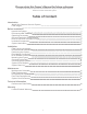
Please retain this Owner’s Manual for future reference. It includes information for operation and maintenance of your Olympia Water Systems Reverse Osmosis water filter system.
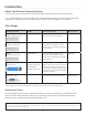
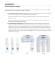
Introduction About Your Reverse Osmosis System Thank you for your purchase of the Olympia Water Systems Reverse Osmosis System. This 5-Stage Reverse Osmosis System was designed and tested to provide high quality drinking water. The following are brief descriptions of each of the 5 stages in this system. Filter Stages Cartridge Filters Model Filter Description Service Life Stage 1 5 Micron Sediment Filter OROS-PRESF Polypropylene filter for removal of sand, silt, dirt and rust particles.
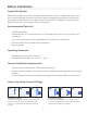
Before Installation Inspect the System Remove the system and all the included components from the box. Inspect the system and the connection fittings to ensure nothing has been damaged during shipment. If any part of the system has been cracked or broken, do NOT proceed with installation. Contact Olympia Water Systems for an exchange or further information.
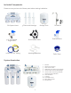
Included Components Please ensure you have all of these parts before starting installation. RO System Head 3 Filters and Housings 3/8” Feed Water Angle Valve 4 Colors of 1/4” Tubing Storage Tank Faucet Kit Drain Saddle Valve Tank Ball Valve Housing Wrenches Teflon Tape System Itemization 9 11 2 1 8 1. 2. 3. 4. 5. 6. 7. 8. 9. 10. 11. 12.
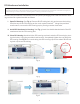
Installation Filter Housing Assembly Remove main system bracket, 3 filters and housings from packaging and assemble the filter housings onto the main system bracket as follows: I. Install Filters into Housings: See Fig. 1. Stand 3 housings upright. Check each housing to ensure the black O-ring is properly seated in its groove. Remove the plastic from the Polypropylene Sediment Filter and place into the 1st Stage housing.
RO Membrane Installation **Important! The tubing connection on the membrane housing cap MUST be removed prior to opening the membrane housing to prevent the tubing connection elbow from breaking and/or cracking inside the housing cap. Remove the provided RO membrane from the plastic packaging and install into the RO housing on the main system bracket as follows: I. Open RO Housing: See Fig. 4. Remove BLUE tubing lock clip and remove the tubing from the cap of the RO housing on the main system bracket.
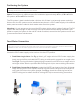
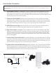
Positioning the System Note Mounting screws for the RO system are NOT included. Space: Ensure there is sufficient space for installation (approximately 16” L x 7” W x 20” H for the system, 12” D x 18” H for the tank). The RO system is best installed under a kitchen sink. If there is not enough space under the kitchen sink, the RO system can be installed where there is a COLD water supply with sufficient water pressure and an outlet to drain waste water from the system.
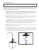
Drain Saddle Connection Important! To avoid possible system drainage noise, install drain saddle on the top of horizontal tailpiece or as low as possible on the vertical tailpiece. Do not install drain saddle close to a garbage disposal outlet as this may cause a blockage in the RO system drain line. I. Drain Saddle Location: See Fig. 10. The drain saddle should be installed above the drain trap on the horizontal or vertical drain tailpiece.
Mounting the Faucet Note If an existing hole in the sink is available, there is no need to drill a hole for the system faucet. If drilling a hole is necessary, be sure to clean up all debris from drilling before installing the faucet. If drilling a hole in the sink or counterop is required to install the faucet, professional installation by a plumber is highly recommended. Olympia Water Systems is not responsible for any damage resulting from faucet installation. I.
Connecting the Tank I. Attach Tank Ball Valve: See Fig. 13. Apply 3-5 wraps of the provided Teflon tape to the threaded output stem on the top of the tank. Screw the provided tank ball valve onto the tank output stem. II. Connect Tank Line to Tank: See Fig. 14. Ensure that tank ball valve is in the OFF position. Insert one end of the YELLOW tubing into the tank ball valve and attach a provided BLUE tubing lock clip to secure tubing connection. III. Connect Tank Line to System: See Fig. 15.
Connecting the System I. Check Tubing Connections: See Fig. 16. Ensure that both ends of all tubing connections are installed and secured with provided BLUE tubing lock clips. II. System Water Inlet Connection: See Fig. 17. Check that the feed water angle valve is in the OFF position. III. Tank Input & Output: See Fig. 18. Ensure that tank ball valve is in the OFF position. System Flow Diagram D Fig. 16 Tubing Connections A. Connect WHITE tubing to Water Supply B.
System Start-Up I. Turn on Feed Water: Turn cold water supply to ON position. See Fig. 17 on page 11. Turn feed water angle valve to ON position to allow water to enter the RO system. II. Open Tank Valve: See Fig. 18 on page 11. Turn tank ball valve to ON position. III. Check for Leaks: Check valves, fittings, tubing connections and housings to ensure there are no leaks. IV. Wait for Tank to Fill: Allow the RO system to run for approximately 3 hours to fill the tank.