
Instructions / Assembly

7
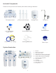
Feed Water Connection
Space: Ensure there is sucient space for installation (approximately 16” L x 7” W x 20” H for
the system, 12” D x 18” H for the tank).
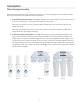
The RO system is best installed under a kitchen sink. If there is not enough space under the
kitchen sink, the RO system can be installed where there is a COLD water supply with sucient
water pressure and an outlet to drain waste water from the system.
Mounting: It is not neccessary to mount the RO system to the wall or inside of cabinet. The RO
system can stand upright on the housings in the sink cabinet without being mounted. If you
prefer to mount the system to the wall or inside of cabinet, ensure that the system can be easi-
ly removed for future maintenance.
Important!
The system must be connected to the COLD water supply only. If the cold water supply valve cannot turn o the water at
installation location, the main water supply to the house must be shut-o before installation.
Locate the COLD water supply valve and turn it to the OFF position.
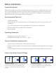
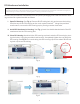
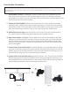
I. Feed Water Angle Valve: See Fig. 7. Attach 3/8” angle valve to COLD water supply line.
Insert one end of the provided WHITE tubing to white quick connection on angle valve.
See Fig. 8. Turning clockwise, tighten tubing connection until RED line on angle valve is
no longer visible. Attach a provided BLUE tubing lock clip to secure tubing connection.
II. Feed Water Connection to System: Locate the WHITE cap insert at the front of the 1st
Stage housing on the main system bracket. Remove BLUE tubing lock clip and WHITE
cap insert from the main system bracket. See Fig. 9. Insert the remaining end of the
WHITE tubing and re-attach the BLUE tubing lock clip to secure tubing connection.
Fig. 7 Fig. 8 Fig. 9
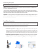
Note
Mounting screws for the RO system are NOT included.
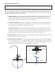
Positioning the System