
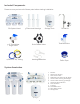
Instructions / Assembly

8
Drain Saddle Connection
Install
Drain Saddle
at Either
Location
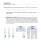
Important!
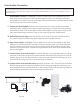
To avoid possible system drainage noise, install drain saddle on the top of horizontal tailpiece or as low as possible on the
vertical tailpiece. Do not install drain saddle close to a garbage disposal outlet as this may cause a blockage in the RO
system drain line.
I. Drain Saddle Location: See Fig. 10. The drain saddle should be installed above the
drain trap on the horizontal or vertical drain tailpiece. If you are installing on the hori-
zontal tailpiece, position the hole on the top side of the tailpiece to prevent waste water
from owing back into the RO system.
II. Prepare the Drain Saddle: Remove nuts and screws from drain saddle to separate
the plastic drain saddle pieces. Remove backing and pre-cut hole from the provided
self-adhesive foam seal. Attach foam seal to drain saddle by lining up the hole on the
foam with the tubing connection hole on the inside of the drain saddle piece.
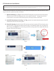
III. Drill Drain Hole into Pipe: Mark the position of the hole on the drain tailpiece. Drill a
1/4” hole through one side of the drain tailpiece at the marked location.
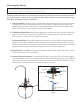
IV. Align Drain Saddle: See Fig. 11. Position both halves of the drain saddle on the drain
tailpiece so that the tubing connection is lined up with the hole in the drain tailpiece.
Use the screws and nuts to clamp the two halves of the drain saddle onto the drain
tailpiece. Ensure that there is equal spacing between each of the drain saddle halves.
Do not overtighten.
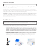
V. Connect Drain Line to the System: Locate the BLACK cap insert attached to the ow
restrictor on the back of the main system bracket. Remove BLUE tubing lock clip and
BLACK cap insert on the ow restrictor. Insert one end of the BLACK tubing and re-at-
tach the BLUE tubing lock clip to secure tubing connection.
VI. Connect Drain Line to Saddle Valve: Measure and mark 1 1/2” from the free end of the
BLACK tubing. Insert remaining end of the BLACK tubing through the opening in the
drain saddle until the marked location on the tubing is ush with the opening. Attach a
provided BLUE tubing lock clip to secure tubing connection.
Fig. 10
Fig. 11