
- OMEGA OMB-DBK Option Cards/Module User Guide
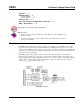

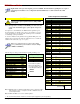

Signal Coupling (JP2 & JP3)
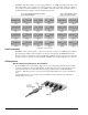
The figure shows jumper settings for selecting AC coupling, 10 Hz or 0.1 Hz High Pass Filter (HPF), or
DC coupling.
Signal coupling is application specific. 10 Hz HPF suits most applications for acceleration measurements
on “light” structures. When performing seismic measurements (or measurements on “massive" structures)
the 0.1 Hz HPF rejects the DC bias component while preserving the low-frequency signals.
JP2 Default: 0.1 Hz
JP3 Default: 0.1 Hz
DC coupling may be used when making a voltage mode measurement.
CAUTION
When the input signal is DC-coupled, the current source must be deselected (Jumper JP4
and/or JP5 removed). Failure to do so could result in damage to the transducer.
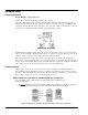
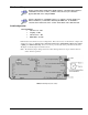
Current Source for Transducer Biasing (JP4 & JP5)
The DBK4 provides a current source for transducer biasing. Bias current is selected (enabled or disabled)
via jumpers JP4 (channel 0) and JP5 (channel 1) as shown in the figure.
CAUTION
When the input signal is DC coupled, the current source must be “off-line” (jumper
removed) to protect the transducer. While DC coupled, the output voltage of the current
source can approach 30 V depending on the output impedance of the transducer.
DBK4, pg. 4 958293 DBK Option Cards and Modules