
- OMEGA OMB-DBK Option Cards/Module User Guide

DBK5, pg. 2
879895 DBK Option Cards and Modules
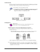
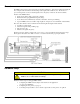
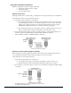
The 4 channels are optically isolated from the Daq Device and from each other. Isolation allows the loop
voltages to float beyond the Daq Device’s common mode range. An externally powered loop allows the
DBK5 to continue to modulate the loop current in the event of a fault or power loss in the Daq Device. If
the loop is powered-up before the Daq Device, the DBK5 will maintain the loop current at 4 mA. After a
fault, the DBK5 will maintain the loop current at the last level set.
Hardware Setup
Card Configuration
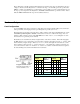
Up to four DBK5 cards can be assigned to a single Daq device channel. With 16 Daq device channels, 4
cards per channel, and 4 inputs per card, up to 256 inputs are possible (16 x 4 x 4).
Each card must appear unique to the Daq device. Micro-switches 1 through 4 (On DIP switch S1) set the
card address for the Daq device channel. A card address can be set to a value in the range of 0 to 15,
inclusive. Micro-switches 7 and 8 set the sub address to a value of 0, 1, 2, or 3 to distinguish one card
from another, for a given Daq device channel.
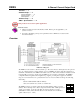
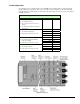
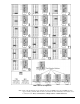
Both addresses are determined by binary-weighted values of the micro-switches. In the following figure
the DIP switch is set for a card address of 15 since micro-switches 1 through 4 are in the “1” position. This
means the binary weights add up to fifteen (8 + 4 + 2 + 1). In the same figure the sub address is 3, since
micro-switches 7 and 8 are in the “1” position giving us 2 + 1. Note that micro-switches 5 and 6 are not
used. Since addresses start at “0” instead of “1,” a card’s 15 / 3 address would mean that it is assigned to
the sixteenth Daq device channel and that it is the fourth card.
Switch Settings & Resulting Addresses
Switch 1-4
Settings
Switch 7-8
Settings
1 2 3 4
Resulting
Card
Address
* * 7 8
Resulting
Sub
Address
0 0 0 0
0
0 0
0
0 1 0 1
5
0 1
1
1 1 0 0
12
1 0
2
Configuration DIP Switch
Shown with a Card Address of
15 and a Sub Address of 3.
1 1 1 1
15
1 1
3
8 4 2 1 -- 2 1 --
Weights associated with switches when set to “1”
*Micro-switches 5 and 6 are not used.