
- OMEGA OMB-DBK Option Cards/Module User Guide
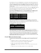

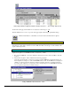

Analog Input Channel Configuration Window, Button and Screen … “User Scaling” Tab Selected
For all of the strain gage channels that are to be adjusted, set their ranges to
+5V.
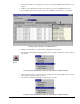
Click the
DBK Parameters tab to expose the strain gage signal conditioning programmable settings.
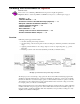
Click the Attach button to substantiate a connection between the PC and the LogBook.
Adjust the Excitation - DBK16
For DBK16, set the excitation voltage for the transducer by adjusting the trimpot labeled EXC and
measuring the voltage with a voltmeter across the +EXC and -EXC on the bridge or at the terminals of the
signal conditioning module.
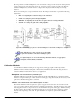
Adjust the Excitation - DBK43A
DBK43A is equipped with a switch that allows the excitation voltage to be read by the LogBook and
displayed in LogView. For all
DBK43A units to be adjusted, you must:
1.
Reposition the DBK43A’s “physical” calibration switch (located next to the Power LED) to the CAL
position.
2.
Select CAL in LogView. This is detailed in the following paragraph.
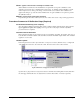
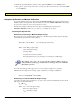
Open the
LogBook Hardware Configuration window and select DBK43A (see following figure). In
the Configurations settings box, set the CAL/NORM Switch to CAL. If the DBK43A is not displayed
click the + to the left of the base channel (to which it is attached), this action expands the hardware
tree in the
LogBook Hardware Configuration window. Repeat this process for all DBK43A units that
are to be adjusted. Click OK to lock in the changes.
Setting a DBK43A Cal/Norm Switch to “CAL”
DBK16, pg. 18 879895 DBK Option Cards and Modules