
- OMEGA OMB-DBK Option Cards/Module User Guide


V
D
= (150/150) * 5 * 0.90 = 4.5V
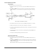
For DBK16, only … Externally apply the shunt resistor and set the voltage to V
D
, as derived above for each
transducer. This is done by adjusting the trimpots labeled GAIN and SCALE for the associated channel.
The GAIN trimpot is used for course adjustment; and the SCALE trimpot for fine-tuning.
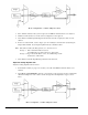
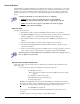
For DBK43A only … DBK43 is equipped with a physical switch that allows the shunt to be applied when
directed by the software. For each DBK43A to be adjusted, move this physical switch from NORM to CAL.
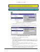
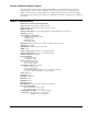
2. In LogView, open the LogBook Hardware Configuration window and select the DBK43A.
LogBook Hardware Configuration, Button and Screen
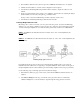
3.
Select the DBK43A from the LogBook Hardware Configuration window’s hardware tree.
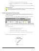
4.
Set the list box to the right to CAL. If the DBK43A is not displayed click the + to the left of
the base channel to which it is attached to expand the hardware tree.
Setting a DBK43A Cal/Norm Switch to “CAL”
5. Repeat this process for each DBK43A that is to be adjusted.
6.
Click OK to lock in the changes.
7.
Open the Analog Input Channel Grid. In the Param1 column (see page 19 for location), select
all of the DBK43A channels that are to be adjusted. Select
Mode = Shunt from the drop down
list above the grid. Turn off all the channels in the system except for those DBK43A channels
that are to be adjusted.
8.
Click the Download button to send the current configuration to the LogBook.
9.
Select Indictors \ Enable Input Reading Column from the menu bar to display the excitation
values for each channel.
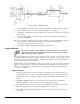
10.
Set the voltage to V
D
, as derived above, for each transducer. This is accomplished by adjusting
the trimpots labeled GAIN and SCALE for the associated channel. The GAIN trimpot
provides for course adjustment. The SCALE trimpot provides for fine tuning.
DBK Option Cards and Module 879895 DBK16, pg. 29