Servicing USA and Canada: Call OMEGA Toll Free USA Canada One Omega Drive, Box 4047 976 Berger Stafford, CT 063070047 Laval (Quebec) HILL 5A1 Telephone: (203) 359-1660 Telephone: (514) 856-6928 FAX: (208) 369-7700 PAX: {514} 856-6386 Sales Service: 1-800-826-6342 / 1-800-TC-OMEGA® Customer Service: 1-800-622-2378 / 1-800-622-BEST™ Engineering Service: 1-800-872-9436 / 1-800-USA-WHEN™ TELEX: 996404 EASY LINK: 62968934 CABLE OMEGA Servicing Europe: United Kingdom Sales and Distribution Fencer 25 Swanning ton
TABLE OF CONTENTS DB-387 SECTION DESCRIPTION PAGE 1 Introduction 1 Description i Unpacking 1 AC Operation 2 Cattery operation 2 Instrument test procedure 3 2 Calibration and Making a Measurement 6 3 Temperature Compensation 8 4 Temperature Coefficient 10 5 Use of Recorder Output 12 6 Use with a Printer or Computer 13 7 Plating 16 g Troubleshooting 17 9 Accessories 19 10 Specifications 20 Appendix ! Cell Constants 21 Appendix 2 Conductivity Solutions 22
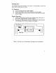
SECTION 1 Introduction Description The OMEGA® DB-387 Conductivity Meter is a precision microprocessor-controlled auto-ranging digital conductivity meter with the ability to measure Total Dissolved Solids (TD, Resistivity and Temperature. The meter has a wide range of features, which include temperature compensation with an adjustable temperature coefficient. Unpacking Remove the Packing List and verify that you have received all equipment.
Setting Up The instrument can be used on battery or AC power, It is not necessary to remove the battery before transferring to AC power, AC Operation ® Use only the approved power adapter supplied . ® Check that the adapter is the correct voltage for your power supply # Plug the adapter into the power socket on the back of the meter then connect to the AC supply. Battery Operation ® Battery should always be used 1o protect calibration data in the event of a power failure.
Instrument Test Procedure ® Switch on and ensure the meter is in Conductivity mode and calibrated (Press Mode key to defect Conductivity mode and press Clear key for 5 seconds to clear calibration data). With the conductivity cell disconnected the display will now read (or 0.000 mS/m). ® Select TDS mode (press Mode key), 0.000 mg/L ® Select Resistivity mode (press Mode key); display should show over-range reading. ® Select °C mode (press Mode key), displayed value should be in the range 0.
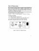
Units of Measurement With the DB-387 Conductivity Meter it is possible to express conductivity and resistivity values with two different types of multiples. The coherent system of units adopted by ISO (CUPPA) known as the SI unit, defines conductivity and resistivity to be expressed as multiples of per meter rather than the older c.g.s. units which expressed values as a multiple of per centimeter. The relationship between the two multiples is as follows:Conductivity 1 Msgr = 100 Ms and Resistivity 10 = 0.
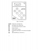
fads Figure 3: Front Panel e G Calibration Keys, alter displayed value Enters displayed value as calibration data Clears calibration data when pressed for 5 seconds Displays cell constant Displays temperature coefficient ~Transmits data to printer/computer.
SECTION 2 Calibration and Measurement m——— —— me—— meme— For accurate results, it is important to remember that when transferring from one solution to another, the cell should be rinsed using DE-ionized water and blotted dry. This will prevent contamination of your sample due to carry-over. For the most accurate measurements, use a calibration solution as close as possible to the value of the sample. REFER TO FIGURES Using a (K=100/m ) conductivity cell © Switch on the power ON/OFF switch on the back panel.
Note: All measurements are automatically temperature compensated by means of a theorist device located in the conductivity cell head (See Section 3 page 8). This can also be used for temperature measurement by selecting °C mode. O Using conductivity cells with other cell constants If the cell constant is already known or has been found by previously calibrating using the technique above, it may be entered directly.
SECTION 3 Temperature Compensation —— wampum— in order to make meaningful inter-sample comparisons of conductivity, the DB-387 electronically compensates to a fixed temperature called the ‘base’ temperature. This is carried cut automatically by means of a theorist in the cell head, or manually by adjusting the displayed value in °C mode to the sample temperature.
O Using No Temperature Compensation © Select °C function and adjust the displayed value using the 44 keys to the base temperature being used. ® Press the %/°C key and adjust the temperature coefficient value to 094/°C using the 1 and keys. © Measure the temperature of the conductivity calibration solution by reconnecting the temperature probe or using a separate thermometer. © Refer to the KCl values given in Appendix 2 and calibrate to the value given in the table for the temperature of the sample.
SECTION 4 Temperature Coefficients T The conductivity of electrolytes changes with temperature. The rate of this change is termed the temperature coefficient and is different for all electrolytes. For most applications where the temperature is unlikely to fluctuate, the default value of is acceptable. This applies to most weak aqueous solutions in the range of 10 13,000uS7cm. If more accurate temperature compensation is required then the exact temperature coefficient for the sample should be determined.
Orienteering Known Temperature Coefficient Values If the temperature coefficient value of the solution is already known either by previously using the above technique or by some other means, it may be entered as follows.~ © Select the %°C function, clear any previous value (press the Clear key for 5 seconds), ® Adjust the displayed value to the desired reading using the 44 keys. © The temperature coefficient has now been set. Select measurement mode required.
SECTION 5 Use of the Recorder Output REFER TO THE RECORDER INSTRUCTIONS © Connect the recorder, via the red and black 4mm recorder sockets on the back panel. (Red POSITIVE and Black NEGATIVE) (Figure 2). © Ensure that the recorder is set for the appropriate range, i.¢: MODE Ranger) DISPLAY RECORDER Cod 0-200 1000S/om 100mv TDS 0200 666mg/L 66.6mV Res 0-200 10.0MQ.cm 18.0mV °C *200 25.0°C 25.
SECTION 6 Operation with a Printer or Computer Operation with a Printer Connect a pinier (set at 1200 Baud) to (he meter via the R8232C port on the back of the meter. Follow the calibration procedure given in SECTION 2 To print out a sample reading, press the Send key. The first time the key is pressed the following printout is obtained. [CONS =1000pS/om Pressing and releasing the Send key subsequently, will result in a printout of the displayed reading and temperature only.
Operation with a computer Connect a computer using 1200 Baud via the R8232C port on the back of the meter. A computer program is required to receive and send characters from the computer.The current readings can be sent to the computer manually by pressing the Send Key. Each line is terminated with a CR LF (Carriage return line feed). All characters are ASCII printable alpha-numeric. TWO commands CA and RD can be sent from the computer. QCA send calibration data COMMAND CA 1CRLF CONS = 1413p8/cm CR LF K =0.
SECTION 6 Operation with a Printer or Computer QRD send current readings COMMAND RD CONS = 1413uS/om CR LF TDS = 944mg/i. CR LF RES = 0.
SECTION 7 Plating When using platinum plate conductivity cells, it is important to keep the plates covered with a platinum oxide film (i.c. fine black deposits over the entire plate surface). Should the platinum oxide film deteriorate, the following procedure should be carried out to restore a well deposited black film. Cleaning © DE-grease in a dilute solution of liquid detergent. Wash in chronic acid if using glass-platinum cells. © Rinse in DE-ionized water. © Rinse with 1 Molar nitric acid.
SECTION 8 TROUBLESHOOTING Symptom No Display "BAT" flag displayed Display reads zero Display shows — on left hand side Drifting Readings Poor linearity Flashing °C flag when temperature probe connected Probable Cause(s) Power supply disconnected -~ Battery is flat or not installed baptistery low Cell disconnected Cell not immersed in solution Cell is open circuit -Select correct range Solution outside the range of the instrument ~Cell Contaminated Conductivity cell needs replicating ~Faulty temperature prob
Error Codes PRO Temperature probe malfunctioning E8 Serial Code malfunction In the event of a malfunction, it is important to pinpoint the problem to either the instrument or the cell. If a spare cell is available, substitute it for the one in use. There are no user serviceable parts in this instrument. Please ensure that the meter together with all accessories is returned to OMEGA Engineering Inc. with a full description of the symptoms of the problem.
SECTION 9 Accessories Available From OMEGA Engineering Inc All cells listed have automatic temperature compensation (CATCH. Standard lead length is I meter. Other lead lengths can be made to order.
SECTION 10 Specifications Conductivity: Ranges and resolution: Accuracy: TDS: Ranges and resolution: Accuracy: Resistivity: Ranges and resolution: Accuracy: Temperature: Range: Resolution: Accuracy: Temperature Compensation: Reference Temperature: Temperature Coefficient: Recorder Output: Plating Output: RS232: Power: Instrument size: Instrument weight: 0 or 2.000mS/m 0 or 20.00 Ms 0 2000 psalm or 200.0mS/m 0 20.6 Memphis or 2000mS/m 0 200mS/em or 20.008/m 40.3% of reading 0 13.20 mg/L 0 132.0 mg/L.
Appendix 1 Cell Constants Conductivity cells with different cell constants can be used to achieve greater accuracy, or used to make difficult measurements easier. Selection of the correct cell constant is dependent on the conductivity range of your sample. Conductivity of various waters and common solutions, together with the most suitable cell constants are given below. K = (K = For measurements of solutions with very [low conductivity, e.g.
WARRANTY i OMEGA warrants this unit to be free of defects in materials and workmanship and to give satisfactory service for & period of 13 months from date of purchase. OMEGA Warranty adds an additional one {1) month grace period to the normal one (1} year product warranty to cover handing and shipping time, This ensures that our customers receive maximum coverage on each product.
OMEGA...