Table of Contents Preface About this User's Guide .......................................................................................................................5 What you will learn from this user's guide ......................................................................................................... 5 Conventions used in this user's guide ................................................................................................................. 5 Where to find more information ....
OMB-DAQ-2416-4AO User's Guide Chapter 4 Calibrating the OMB-DAQ-2416-4AO ................................................................................................24 Calibration methods .......................................................................................................................................... 24 Factory calibration ...........................................................................................................................................................
Preface About this User's Guide What you will learn from this user's guide This user's guide explains how to install, configure, and use the OMB-DAQ-2416-4AO so that you get the most out of its analog I/O, thermocouple (TC) input, digital I/O, and counter/timer I/O features. This user's guide also refers you to related documents available on our web site, and to technical support resources.
Chapter 1 Introducing the OMB-DAQ-2416-4AO Overview: OMB-DAQ-2416-4AO features The OMB-DAQ-2416-4AO is supported under popular Microsoft® Windows® operating systems. The OMBDAQ-2416-4AO is a multifunction measurement and control board designed for the USB bus. The OMB-DAQ-2416-4AO is a full-speed, multiplexed 24-bit measurement system that provides up to 16 differential and up to 32 single-ended (SE) analog inputs. It offers software-selectable analog input ranges of ±20 V, ±10 V, ±5 V, ±2.5 V, ±1.
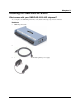
Chapter 2 Installing the OMB-DAQ-2416-4AO What comes with your OMB-DAQ-2416-4AO shipment? As you unpack your OMB-DAQ-2416-4AO, verify that the following components are included.
OMB-DAQ-2416-4AO User's Guide Installing the OMB-DAQ-2416-4AO Optional components Expansion devices that are compatible with the OMB-DAQ-2416-4AO must be ordered separately. If you ordered any of the following products with your device, they should be included with your shipment: OMB-AI-EXP32 Analog input expansion module adds up to 16 differential or 32 single-ended inputs to the OMB-DAQ-24164AO.
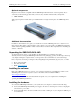
OMB-DAQ-2416-4AO User's Guide Installing the OMB-DAQ-2416-4AO When you connect the OMB-DAQ-2416-4AO for the first time, a Found New Hardware message opens as the OMB-DAQ-2416-4AO is detected. When the message closes, the installation is complete. The power LED (bottom LED) blinks during device detection and initialization, and then remains solid if properly detected. If not, check if the OMB-DAQ-2416-4AO has sufficient power.
OMB-DAQ-2416-4AO User's Guide Installing the OMB-DAQ-2416-4AO Caution! Turn off power to all devices connected to the system before making connections. Electrical shock or damage to equipment can result even under low-voltage conditions. Caution! Always handle components carefully, and never touch connector terminals or circuit components unless you are following ESD guidelines in an appropriate ESD-controlled area.
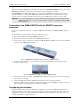
OMB-DAQ-2416-4AO User's Guide Installing the OMB-DAQ-2416-4AO Screw terminal pin out – differential No connection Channel 0 HI Channel 0 LO No connection No connection Channel 1 HI Channel 1 LO No connection No connection Channel 2 HI Channel 2 LO No connection No connection Channel 3 HI Channel 3 LO No connection NC CH0H CH0L NC NC CH1H CH1L NC NC CH2H CH2L NC NC CH3H CH3L NC 1 2 3 4 5 6 7 8 9 10 11 12 13 14 15 16 49 50 51 52 53 54 55 56 57 58 69 60 61 62 63 64 NC CH15L CH15H NC NC CH14L CH14H NC NC
OMB-DAQ-2416-4AO User's Guide Installing the OMB-DAQ-2416-4AO Screw terminal pin out – single-ended No connection Channel 0 Channel 16 No connection No connection Channel 1 Channel 17 No connection No connection Channel 2 Channel 18 No connection No connection Channel 3 Channel 19 No connection NC CH0H CH0L NC NC CH1H CH1L NC NC CH2H CH2L NC NC CH3H CH3L NC 1 2 3 4 5 6 7 8 9 10 11 12 13 14 15 16 49 50 51 52 53 54 55 56 57 58 69 60 61 62 63 64 NC CH15L CH15H NC NC CH14L CH14H NC NC CH13L CH13H NC NC CH
Chapter 3 Functional Details This chapter contains detailed information on all of the features available from the board, including: Device components Functional block diagram and mechanical drawings Signal descriptions Signal diagrams using default or conventional device settings OMB-DAQ-2416-4AO components These OMB-DAQ-2416-4AO components are shown in Figure 6 and Figure 7.
OMB-DAQ-2416-4AO User's Guide Functional Details LEDs When the OMB-DAQ-2416-4AO is connected to a computer, in its normal idle state both LEDs are lit solid green. Power LED The Power LED is the top LED on the right side of the OMB-DAQ-2416-4AO housing. The Power LED blinks when you plug the power supply into the OMB-DAQ-2416-4AO, and continues to blink while the device initializes the hardware.
OMB-DAQ-2416-4AO User's Guide Functional Details Mechanical drawings 4.800 Figure 8. OMB-DAQ-2416-4AO internal dimensions Figure 9.
OMB-DAQ-2416-4AO User's Guide Functional Details Block diagram Figure 10 shows a simplified block diagram of the OMB-DAQ-2416-4AO. This device provides all of the functional elements shown in the figure. Figure 10.
OMB-DAQ-2416-4AO User's Guide Functional Details Analog/TC input terminals You can connect up to 32 single-ended analog input connections or up to 16 differential analog/TC input connections to these screw terminal pins.
OMB-DAQ-2416-4AO User's Guide Functional Details The OMB-DAQ-2416-4AO also provides an open thermocouple detection (OTD) feature for each of the analog input channels configured for thermocouple measurement. This feature is automatically enabled as part of the overall acquisition process, and detects if an open-circuit condition exists at the thermocouple sensor. The OMB-DAQ-2416-4AO provides electrostatic discharge (ESD) protection for each of the thermocouple inputs.
OMB-DAQ-2416-4AO User's Guide Functional Details Maximum multiple-channel throughput: 1 n 1 data rate 640 μs where n is the number of channels Refer to the tables in the Throughput rate section of the Specifications chapter for details. This drop-off in throughput rate is due to the OMB-DAQ-2416-4AO's noise filtering feature. You can control the amount of the noise filtering by adjusting the data rate setting.
OMB-DAQ-2416-4AO User's Guide Functional Details Resolution = 19.6 bits Resolution = 20.6 bits 640 µs delay before next sample taken Figure 13. OMB-DAQ-2416-4AO data rate vs. resolution example Input isolation The OMB-DAQ-2416-4AO is an isolated data acquisition device. The analog I/O, digital I/O, counters, and all the digital control/timing are referenced to an isolated ground as shown in the figure below.
OMB-DAQ-2416-4AO User's Guide Functional Details Analog output terminals (VDAC0 through VDAC3) The OMB-DAQ-2416-4AO has four 16-bit analog output channels with a ±10 V output range. Analog outputs can be updated at a maximum rate of 1000 samples per second (S/s). Digital I/O Up to eight digital I/O lines are available in each OMB-DAQ-2416-4AO. Digital input voltage ranges of 0 to +15V are permitted, with thresholds of 0.6 V (low) and 2.6 V (high).
OMB-DAQ-2416-4AO User's Guide Functional Details Figure 16. Location of screws connecting bottom and top sections of case Figure 17. Location of JP1 4. To pull the digital pins down to ground, place the shorting block across pins 2 and 3 (refer to the jumper orientation shown in Figure 17). To pull the digital pins up to +5V, place the shorting block across pins 1 and 2.
OMB-DAQ-2416-4AO User's Guide Functional Details +5 V JP1 +V 47 kΩ Internal jumper disabled (placed on center pin only) External pull-up resistor DIO0 DIO1 DIO2 DIO3 DIO4 DIO5 DIO6 DIO7 Figure 18. Digital I/O external resistor configuration Counter input terminals (CTR0, CTR1) Two 32-bit event counters are built into the OMB-DAQ-2416-4AO. Each counter accepts frequency inputs up to 1 MHz. Refer to the "Screw terminal pin out" diagrams starting on page 11 for the location of these pins.
Chapter 4 Calibrating the OMB-DAQ-2416-4AO The OMB-DAQ-2416-4AO is initially calibrated using an NIST-traceable calibration method. This method stores a correction factor for each AIN and AOUT range in non-volatile memory on the device at the time of calibration. Allow a 45 minute warm-up period before calibrating the OMB-DAQ-2416-4AO. Calibration methods Factory calibration You can return the OMB-DAQ-2416-4AO once a year to Omega Engineering for a new factory calibration and calibration certificate.
Chapter 5 Specifications All specifications are subject to change without notice. Typical for 25 °C unless otherwise specified. All specifications apply to all temperature and voltage input channels unless otherwise specified. Specifications in italic text are guaranteed by design. Analog input Table 1.
OMB-DAQ-2416-4AO User's Guide Specifications Parameter Conditions Specification CJC sensor accuracy 15 °C to 35 °C 0 °C to 55 °C ±0.15 °C typical ±0.5 °C maximum Note 1: Placing a notch of the A/D digital filter at 60 Hz (setting A/D data rate = 60 S/s, 10 S/s, 5 S/s or 2.5 S/s) further improves the common mode rejection of this frequency. Channel configurations When any item is changed, the firmware stores channel configurations in the EEPROM of the isolated microcontroller.
OMB-DAQ-2416-4AO User's Guide Specifications Connect thermocouples to the OMB-DAQ-2416-4AO such that they are floating with respect to GND (pins 18, 36, 39, 42, 44, 46, 66, 81, 84, 93, and 94). When configuring thermocouple sensors, keep any stray capacitance relative to GND (pins 18, 36, 39, 42, 44, 46, 66, 81, 84) as small as possible to avoid settling time and accuracy errors. The OMB-DAQ-2416-4AO GND and DGND pins are isolated from earth ground.
OMB-DAQ-2416-4AO User's Guide Specifications Table 5. K type thermocouple accuracy specifications, including CJC measurement error. All specifications are (±). A/D data rate Sensor temperature range Accuracy error maximum Accuracy error typical Tempco (°C/°C) 3750 S/s -210 °C 0 °C 1372 °C -210 °C 0 °C 1372 °C -210 °C 0 °C 1372 °C -210 °C 0 °C 1372 °C -210 °C 0 °C 1372 °C -210 °C 0 °C 1372 °C -210 °C 0 °C 1372 °C -210 °C 0 °C 1372 °C -210 °C 0 °C 1372 °C -210 °C 0 °C 1372 °C -210 °C 0 °C 1372 °C 2.
OMB-DAQ-2416-4AO User's Guide Specifications Table 6. N type thermocouple accuracy specifications, including CJC measurement error. All specifications are (±). A/D data rate Sensor temperature range Accuracy error maximum Accuracy error typical Tempco (°C/°C) 3750 S/s -200 °C 0 °C 1300 °C -200 °C 0 °C 1300 °C -200 °C 0 °C 1300 °C -200 °C 0 °C 1300 °C -200 °C 0 °C 1300 °C -200 °C 0 °C 1300 °C -200 °C 0 °C 1300 °C -200 °C 0 °C 1300 °C -200 °C 0 °C 1300 °C -200 °C 0 °C 1300 °C -200 °C 0 °C 1300 °C 3.
OMB-DAQ-2416-4AO User's Guide Specifications Table 7. R type thermocouple accuracy specifications, including CJC measurement error. All specifications are (±).
OMB-DAQ-2416-4AO User's Guide Specifications Table 8. S type thermocouple accuracy specifications, including CJC measurement error. All specifications are (±).
OMB-DAQ-2416-4AO User's Guide Specifications Table 9. B type thermocouple accuracy specifications, including CJC measurement error. All specifications are (±).
OMB-DAQ-2416-4AO User's Guide Specifications Table 10. E type thermocouple accuracy specifications, including CJC measurement error. All specifications are (±). A/D data rate Sensor temperature range Accuracy error maximum Accuracy error typical Tempco (°C/°C) 3750 S/s -200 °C 0 °C 1000 °C -200 °C 0 °C 1000 °C -200 °C 0 °C 1000 °C -200 °C 0 °C 1000 °C -200 °C 0 °C 1000 °C -200 °C 0 °C 1000 °C -200 °C 0 °C 1000 °C -200 °C 0 °C 1000 °C -200 °C 0 °C 1000 °C -200 °C 0 °C 1000 °C -200 °C 0 °C 1000 °C 2.
OMB-DAQ-2416-4AO User's Guide Specifications Table 11. T type thermocouple accuracy specifications, including CJC measurement error. All specifications are (±). A/D data rate Sensor temperature range Accuracy error maximum Accuracy error typical Tempco (°C/°C) 3750 S/s -200 °C 0 °C 400 °C -200 °C 0 °C 400 °C -200 °C 0 °C 400 °C -200 °C 0 °C 400 °C -200 °C 0 °C 400 °C -200 °C 0 °C 400 °C -200 °C 0 °C 400 °C -200 °C 0 °C 400 °C -200 °C 0 °C 400 °C -200 °C 0 °C 400 °C -200 °C 0 °C 400 °C 2.821 °C 1.
OMB-DAQ-2416-4AO User's Guide Specifications Analog input DC voltage measurement accuracy Table 12. DC Accuracy components and specifications. All values are (±) Range A/D data rate Gain error (% of reading) Offset error INL error (% of range) Absolute accuracy Gain temperature coefficient (% reading/°C) Offset temperature coefficient (µV/°C) ±20 V 3750 S/s 2000 S/s 1000 S/s 500 S/s 100 S/s 60 S/s 50 S/s 25 S/s 10 S/s 5 S/s 2.
OMB-DAQ-2416-4AO User's Guide Range ±0.625 V ±0.3125 V ±0.15625 V ±0.078125 V Specifications A/D data rate Gain error (% of reading) Offset error INL error (% of range) Absolute accuracy Gain temperature coefficient (% reading/°C) Offset temperature coefficient (µV/°C) 2000 S/s 1000 S/s 500 S/s 100 S/s 60 S/s 50 S/s 25 S/s 10 S/s 5 S/s 2.5 S/s 3750 S/s 2000 S/s 1000 S/s 500 S/s 100 S/s 60 S/s 50 S/s 25 S/s 10 S/s 5 S/s 2.
OMB-DAQ-2416-4AO User's Guide Range Specifications A/D data rate Gain error (% of reading) Offset error INL error (% of range) Absolute accuracy Gain temperature coefficient (% reading/°C) Offset temperature coefficient (µV/°C) 60 S/s 50 S/s 25 S/s 10 S/s 5 S/s 2.5 S/s 0.035 0.035 0.035 0.035 0.035 0.035 6 µV 6 µV 6 µV 6 µV 6 µV 6 µV 0.0009 0.0009 0.0009 0.0009 0.0009 0.0009 33.866 µV 34.026 µV 33.933 µV 33.937 µV 33.969 µV 33.934 µV 0.0006 0.0006 0.0006 0.0006 0.0006 0.
OMB-DAQ-2416-4AO User's Guide Specifications Table 15. RMS noise performance specifications (µVRMS) A/D data rate Range ±20 V ±10 V ±5 V ±2.5 V ±1.25 V ±0.625 V ±0.3125 V ±0.15625 V ±0.078125 V 3750 S/ s 2000 S/ s 1000 S/ s 500 S/ s 100 S/ s 60 S/ s 50 S/ s 25 S/ s 10 S/ s 5 S/ s 2.5 S/ s 34.90 19.22 8.60 4.99 2.81 2.86 2.32 2.01 28.32 15.17 7.21 4.36 2.66 2.51 2.24 2.55 19.22 10.87 5.18 2.72 2.10 1.28 1.24 1.13 15.17 6.83 3.92 2.15 1.41 1.12 1.05 1.00 8.67 4.62 2.46 1.14 0.83 0.81 0.
OMB-DAQ-2416-4AO User's Guide Specifications Throughput rate The single channel throughput rate is calculated using this formula: Maximum throughput Table 18. Single channel throughput rate specifications A/D data rate Maximum throughput (Hz) 3750 S/s 2000 S/s 1000 S/s 500 S/s 100 S/s 60 S/s 50 S/s 25 S/s 10 S/s 5 S/s 2.5 S/s 1102.94 877.19 609.76 378.79 93.98 57.78 48.45 24.61 9.94 4.98 2.
OMB-DAQ-2416-4AO User's Guide Specifications Analog voltage output Unused VDACx output channels should be left disconnected. The OMB-DAQ-2416-4AO output voltage level defaults to 0 V whenever the host PC is reset, shut down or suspended, or if a reset command is issued to the device. The duration of the output transient depends highly on the enumeration process of the host PC. Typically, the output of the OMB-DAQ-2416-4AO is stable after two seconds. Table 20.
OMB-DAQ-2416-4AO User's Guide Specifications Analog input/output calibration Table 24. Analog input/output calibration specifications Parameter Specifications Recommended warm-up time Calibration Calibration interval Calibration reference 45 minutes minimum Firmware calibration 1 year +10.000 V, ±5 mV maximum. Actual measured values stored in EEPROM Tempco: 5 ppm/°C maximum Long term stability: 30 ppm/1000 hours Digital input/output Table 25.
OMB-DAQ-2416-4AO User's Guide Specifications Note 5: The external pull-up is connected to the digital output bit through an external pull-up resistor. Adding an external pull-up resistor connects it in parallel with the internal 47 kΩ pull-up resistor of that particular digital input/output bit. Careful consideration should be made when considering the external pull-up resistor value and the resultant pull-up voltage produced at the load.
OMB-DAQ-2416-4AO User's Guide Specifications Power Table 30. Power specifications Parameter Conditions Specification Supply current (Note 8) External power input (Note 9) External power supply Voltage supervisor limits Quiescent current +5 V user output voltage range User +5V user output current OMB-DAQ-2416-ADAP (included) 4.5 V > Vext or Vext > 5.5 V 4.5 V < Vext < 5.
OMB-DAQ-2416-4AO User's Guide Specifications Screw terminal connector type and pin-out Table 35. Screw terminal connector specifications Connector type Wire gauge range Detachable screw terminal 16 AWG to 30 AWG Screw terminal pin out For additional channel configurations when using the optional AI-EXP expansion device, refer to the "Optional OMB-AI-EXP32 expansion module" section on page 47.
OMB-DAQ-2416-4AO User's Guide Specifications Table 36. 16-channel differential mode pin out Do not connect to terminal block pins labeled "NC.
OMB-DAQ-2416-4AO User's Guide Specifications Table 37. 32-channel single-ended mode pin out Do not connect to terminal block pins labeled "NC.
OMB-DAQ-2416-4AO User's Guide Specifications Optional OMB-AI-EXP32 expansion module Use the OMB-AI-EXP32 (sold separately) for applications that need additional analog/thermocouple input and digital I/O channels. See the Omega Engineering web site for product details. The OMB-AI-EXP32 expansion port is intended to interface with a OMB-DAQ-2416 series product. Do not try to use any of the expansion port pins for any other purpose. Table 38.
OMB-DAQ-2416-4AO User's Guide Specifications Table 39. Multiple-channel throughput rate specifications (Hz), OMB-DAQ-2416-4AO and optional OMB-AI-EXP32 expansion module 3750 S/s 2000 S/s 1000 S/s 500 S/s 100 S/s 60 S/s 50 S/s 25 S/s 10 S/s 5 S/s 2.5 S/s 1 2 3 4 5 6 7 8 9 10 11 12 13 14 15 16 1102.94 551.47 367.65 275.74 220.59 183.82 157.56 137.87 122.55 110.29 100.27 91.91 84.84 78.78 73.53 68.93 877.19 438.60 292.40 219.30 175.44 146.20 125.31 109.65 97.47 87.72 79.74 73.10 67.48 62.66 58.
OMB-DAQ-2416-4AO User's Guide Specifications OMB-AI-EXP32 screw terminal pin out Table 40. 32-channel differential mode pin out Do not connect to terminal block pins labeled "NC.
OMB-DAQ-2416-4AO User's Guide Specifications Table 41. 32-channel single-ended mode pin out Do not connect to terminal block pins labeled "NC.
OMB-DAQ-2416-4AO User's Guide Specifications OMB-DAQ-2416-4AO screw terminal pin out (with OMB-AI-EXP32 attached) Table 42. OMB-DAQ-2416-4AO single-ended mode pin out with OMB-AI-EXP32 connected Do not connect to terminal block pins labeled "NC.