Advanced Measurement Technology User Guide for OmniTek XR Software Version: 1.0.1.
© 2006 Image Processing Techniques Ltd. All rights reserved This documentation contains proprietary information of Image Processing Techniques Ltd. No part of this documentation may be reproduced, stored in a retrieval system or transmitted in any form or by any means, electronic, mechanical, recorded or otherwise without the prior written permission of Image Processing Techniques Ltd. The information contained in this documentation was prepared by Image Processing Techniques Ltd.
Table of Contents 1. USER GUIDE ................................................................................................................6 Introduction..................................................................................................................................................................... 6 From Power-Up.................................................................................................................................................. 6 Quick Start Guide.......
Source Toolbar ................................................................................................................................................. 29 Source Toolbar (Dual Link Option) ................................................................................................................ 29 Main Toolbar.................................................................................................................................................... 30 Crosshair Toolbar.................
Add/Edit item .................................................................................................................................... 62 Item order........................................................................................................................................... 63 Delete item......................................................................................................................................... 63 Playlist save/open/new ..................................
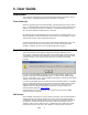
1. User Guide Introduction This user guide assumes that you are familiar with basic Windows techniques, such as using a mouse, manipulating window sizes and positions, scrolling etc. From Power-Up When the operating system has finished booting, and if prompted by the system, please log in. The default software installation places a shortcut to the OmniTek software on the desktop. The software will have been installed into ‘c:\program files\omnitek\omnitek XR’.
If you don’t want to use full screen mode, you can change the default setting by selecting ‘Configuration…’ from the ‘Full Screen’ menu. Clear the tick box marked ‘Startup in fullscreen mode:’, and click OK on the dialogue. Details on Full Screen modes are on page 14. Video Setup Once the system is running normally within ‘Windows, the next thing to do is to set the video standard you will be working in. Normally you will want to use ‘Auto Detect’, which may be set on the ‘Video Standard’ toolbar.
If you have previously saved a system configuration, you can open a configuration, by selecting ‘Open System Configuration’ from the ‘Configuration’ menu. No system configuration files are included with the original installation. Image Choice If you have an OmniTek XR system that also includes the Motion/Capture option, the full ‘Source’ toolbar will be present. If it is not visible, it can be turned on from the ‘Show’ menu on the main application.
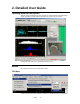
2. Detailed User Guide Opening Window Description With the OmniTek application running, you will see a window similar to that illustrated below, depending on what modules and options are present on your system. Dealing with each area in turn, and starting with the menus… Menus Each function on the menus is described in detail. File Menu The file menu has three main functions, Preferences, Window layouts, and snapshots.
Preferences From the Preferences choice, you can enable automatic resizing of windows when changing standards. This can be useful if you are using the waveform windows at the default size for a given standard, as not all standards use the same aspect ratio. When the OmniTek application is started, it automatically loads the configuration that was active when it was last closed. The second Preference choice here lets the system prompt you for choice of configuration instead.
Show Menu The main desktop application has four work surfaces available. You can just use one. However, if preferred, you can split the various windows amongst the four work surfaces, which may help to keep an uncluttered screen. The Show menu gives access to the four different pages, although you can also use the four buttons available on the bottom right hand side of the status bar (see page 65 for details on status bar).
Run Menu The Run menu is provided to duplicate the transport controls included on the Run toolbar. It is anticipated that the controls will normally be used from the toolbar, as this is usually much quicker to use. However the menu is provided such that automated keyboard macros may be used, as menu items can always be selected by combinations of key presses.
Analyzer Menu The Analyzer menu is shown above. A variety of functions for the main OmniTek XR analyzer module are available here. Functions used most commonly are available from icons on the main toolbar, whilst features that are rarely used can only be controlled from this menu. Each menu item is described in turn. Input to Analyzer Controls whether the main View module looks at the serial input, or at the Generator (only if motion/capture option is present).
Output Menu This menu controls features relating to the output video. OmniTek XR can display a crosshair on the output. The crosshair is always centred over the sample currently displayed in the dataview. The crosshair can appear on the analogue (monitoring) output, or the serial digital output, or on both outputs.
As well as operating within a convention ‘window’, OmniTek XR has many display modes that can operate within a ‘full-screen’ environment. This menu is concerned with these modes. From the initial menu you can directly launch a specific view into full screen mode. When in full screen, press ‘ESCAPE’ to return to the normal view. Pressing ESCAPE again will go directly to full screen, to the view last looked at. By selecting ‘Configuration’, you can adjust various settings.
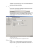
Once you have selected a template layout, the window below will show all currently existing instances of that template layout. It is possible that not all templates will have been used, so for some, the window will be empty. If there are existing instances, they can be edited. To create a new instance, select the ‘Add new instance’ button. A new instance appears, with the window panes unassigned, and the whole thing highlighted in dark red, and an individual pane highlighted in a lighter red.
you wish to use, and press OK (and do not press Enter on the keyboard, as otherwise that will be picked as the hotkey assignment). Note that certain choices are not available, as these are already assigned to the OmniTek application, or to the operating system environment. Once a valid hot key has been assigned, it will be indicated above the right hand corner of the layout image. Subsequent presses of the relevant hot key will switch LAB directly into full screen mode into the chosen layout.
Reprogram Flash At the top of the dialogue box, there is a button called 'Reprogram Flash'. The main video processing on OmniTek products is done using a large FPGA. The firmware for this FPGA may be changed by downloading a new design to the onboard Flash memory. It this way it is possible to improve the video processing remotely. When a new software update is installed, the software should automatically detect the presence of new firmware, and reprogram the flash.
The controls relate only to video generated in the Motion/Capture module. Power on Defaults ‘Power on Defaults’ is used to force the analogue and serial outputs from the OmniTek XR to a chosen video format, within half of one second from power up of the system, and therefore before the operating system has had time to load. The settings will remain in force until the OmniTek XR application has initialized, when the program settings will overwrite the power up settings.
Engineering - Video - Analyzer OmniTek XR always works with actual video data, which as a 10 bit value will be a number from 0 to 1023. Sometimes it is easier to understand the operation of OmniTek XR if these ranges are scaled to more familiar units. By choosing ‘Preferences’ from the File menu of the main application, you will see some options to change the ‘Amplitude measurement units’ from digital levels to Percent IRE, or to Millivolts.
The settings for luma, chroma or gamut ranges and the error mask may be saved in a profile. Click the save range settings button, and the settings will be saved to a named profile. When OmniTek XR is started, the last used profile is automatically loaded. However, a new profile may be loaded at any time. As well as detecting errors, this dialogue provides access to a special mode of operation for the vectorscope, the “luma qualified vectorscope”.
Finally, a variable level of gamma correction maybe applied to the video. Note that whilst the lookup table adjusts how the waveforms and vectorscope are displayed, the data shown in the Dataview window is always the exact data contained upon the serial inputs. If your Dual Link system also includes the optional Motion/capture module, then you can also produce a dual link output from the system. The output can be configured as either single link or dual link.
Engineering – Picture OmniTek XR can detect whether the picture is moving or frozen, or whether the picture has gone to black, or to black and white. The settings for the detectors may be configured here. • • • Motion Content A level of filtering can be applied to the picture. This is designed to accommodate an analog VTR that is parked on a single frame. The picture will be frozen, but the varying analog noise from the VTR will mean that each frame is actually slightly different.
ATC is available in SD and HD, but VITC is only read in SD, and it is necessary to configure which lines are to be used to read the timecode data. The typical lines used for PAL and NTSC are shown above. For ATC, noting that ATC is simply a packet that can contain different types of timecode, it is necessary to specify whether you intend to read LTC, VITC1 or VITC2. Note that the term LTC here refers to LTC data embedded within an ATC packet, not to the older form of LTC transmitted in an analog format.
Engineering - Wide Screen Signalling (Line 23) Reader Configuration The standard OmniTek XR system can detect and decode wide screen signaling data that is contained in line 23 of a PAL/625 signal. XR can interpret the data either as per EN300294, or as modified by ARDSPEC.
Engineering - Teletext Detector Configuration OmniTek XR can detect the presence of teletext data in the incoming video. It is necessary to specify the correct line number that contains the data. This feature only works in SD.
3 Toolbar Icons Beneath the menus there is a row of icons, referred to collectively as the toolbars, which provide direct access to many of the functions contained in the menus. The toolbars shown here is just one arrangement with all of the toolbars activated. Of course, Windows provides the ability to undock or move each toolbar individually, so they may be positioned differently.
A Time Shift recording can be triggered by one of the trigger conditions shown in this dialogue box. It can be based on reaching one of several given VITC or ATC timecode values, or on a specific error condition, such as a CRC error occurring. In all cases, it is possible to remain in Time Shift mode, waiting for the next trigger, anc continuing until the RAM is full, or to capture a specific number of triggered events, or to only capture once, then ask the user whether to continue.
Jump to the end of the clip Enable loop mode for sequence play The Frame box with drop down selection lets you select an individual frame from the sequence for immediate display. The speed box with drop down selection lets you choose a playback speed for the sequence. This can be real time, quarter speed, half speed or double speed. The Record Frames box is where you specify how many frames will be captured during a Time Shift capture.
When operating in dual link modes, the source to the analyzer module, the monitor output and the serial outputs all must be the same, so all either look at the internal test pattern generator (or Frame-store), or they all look at the serial input.
The red ‘triangle’ icon is used to open the Capture dialogue, to capture from the single or (optional) dual link input. The icon to the left of the red triangle icon is used to load an image or sequence previously saved. Full details of the controls within this window start on page 53 of this manual. The next icon opens the mini-pic window, where you can see a representation of the incoming video, or captured sequence.
The data view window will display six columns of data when set into dual link mode, or three columns when in single link mode. The contents of the Data View window may be saved as a .txt file. (See the section on window menus on page 45). The file will include all the data within the scrollable window, so if the window is set to contain 100 samples, then these 100 samples will be saved in that txt file. The data will be stored in the file in whichever base they were being displayed in. I.e.
This button opens a drop down menu that lets you switch between single line view, multi line view, and sweep mode. This control duplicates the drop down at the top of the Region-Of-Interest window, described on page 43. Open the Engineering menu – which is described in full starting on page 17. Crosshair Toolbar Next to these controls, we have the controls for the main cursor position. These show the sample number and line number that the cursor is positioned over.
There are two versions of this toolbar. The above version is present in a basic XR system, whilst the version shown below is present if the option Dual Link module is present. Using the drop down menu is identical to selecting the video format from the Video section of the Engineering dialogue’. The video lock reference is unchanged. If the ‘Auto detect’ button is pressed, then the video lock will automatically switch to ‘serial lock’.
4 XR Windows Waveform Window OmniTek XR has extremely powerful and flexible waveform displays. The necessarily means that there are more controls over waveform display than in conventional products. This section describes the full set of waveform controls that are included as part of the waveform window. The waveform window can operate in one of two distinct modes, depending on whether the complex set of controls for the window are visible of hidden.
Clicking in the highlighted area this time will hide the waveform display controls, and revert to the previous window. There now follows a description of the waveform display controls. OmniTek XR can operate the waveforms in a variety of different fundamental modes, which are selected from the ‘Colour mode:’ drop down control.
can be done far more easily by right click and dragging over a portion of the mini-pic display. The chosen area is highlighted on the mini-pic. The section of the mini-pic marked out is used for waveform generation, so you get waveforms zoomed into that area. To revert to the normal display, you must double click with the right mouse key, over any portion of the mini-pic display. Note that when the area is marked on the mini-pic, the vectorscope also only displays vectors based on information in this area.
The graticule lines can be displayed or hidden, and the graticule text labels can also be displayed or hidden. Amplitude markers may also be overlaid onto the main graticules. These are horizontal lines that can be used to mark out important levels. It is possible to define multiple markers, and change which is displayed, or to display several at a time. Note that the units for both axis of the graticules are customizable, using the global selection on the File/Preferences menu selection.
The Look and feel dialogue can be opened from the Options menu on each of the Waveform, Vectorscope, Histogram or Mini-pic windows. The default page that is active is chosen depending on which window you opened it from. For the waveforms, the colour of the graticule, and of each different waveform element can be individually chosen. When the waveforms breach the thresholds for valid video, (specified in the Engineering dialogue, details on page 20), the waveforms can be coloured in a different colour.
Colour Mode menu This lists the different forms of waveform display that exist. This duplicates the Colour Mode section on the waveform additional controls section, described above. The controls are duplicated for user convenience. Note that although you can select each mode from the menu, you will still need to access the controls within the window to change from parade to vertical format, or to select specific components for display.
The histogram window, like the waveform window, contains a section of controls which can be displayed or hidden on the right hand side of the window. Please see the above section on the Waveform window for details of revealing the window controls. Again like the waveform window, the most commonly used controls are available from the Colour Mode menu.
The Look and Feel controls adjust the filtering controls applied to the module creating the vectorscope display. The Gain control affects the brightness of the vectorscope image, whilst the Gamma of the display can also be varied. Finally the length of the persistence on the display can be adjusted with the Decay control. Other important controls are available on the menu bar of the window.
‘Save snapshot’ will take the current vectorscope data and write it to a named bitmap file. On the Window menu are controls to resize the vectorscope display to match the resolution in which it is being generated. These work in a similar fashion to these controls on the waveform window. Region of Interest Window The Region of Interest window controls some of the less required function, as most of the controls can be achieved by other means.
The default waveform position has pixel 1 at the left of the display, and the last pixel on the right of the display. It is possible to scroll the view of the waveform around, which provides a useful means of examining blanking data. This can be done with the ‘H pos’ slider. The image can be magnified using the ‘H mag’ slider, or numeric data entry, or by clicking on the ‘x10’, ‘x5’ or ‘x2’ boxes. You can select a single line or two line display with the ‘1L’ or ‘2L’ boxes.
The display of the mini-pic defaults to normal, full colour mode. When using the XR in a colorist environment, where brightly coloured displays can be a distraction for the colorist, it may be helpful to switch the mini-pic into the monochrome mode. The mini-pic can also be switched into a blue or green mode, whereby the blue (or green) data is applied to all three channels.
Cage Generator OmniTek XR contains a cage generator. By selecting the cage icon dialogue appears. the Cage To enable the display of a cage, press ‘Enable Cage’. To enable masks, select a mask type from the drop down box. The mask will only be shown if Enable Cage is selected. The OmniTek hardware contains two separate cage generators, one for safe action, and one for safe title. Either can be used in the fixed or adjustable mode.
'Profile' box. If there is a name shown in the profile box, then your settings will be saved to this 'file'. If it is blank, a dialogue box appears to let you enter a new name. Once you have several names in use, they can be selected by using the drop down arrow to the right of the profile box. Hence if you have several settings that you regularly use, these can be stored and recalled, without having to re-enter them. Note that these settings are saved into the registry, not as actual files on disk.
5 Video Checking Features Introduction OmniTek XR has the ability to display real-time status information for audio and video data, and to detect and count various types of errors. Status information and error counts are displayed in two status windows, one for video and one for audio. Video Status/Error detection The Video status box has two main modes of operation. This is Report View, and normal view. In report view, there are no buttons on the Video Status window, so it only reports information.
The following information is displayed in the Video Status box General video status parameters • Input standard - Shows what standard has been detected (if in auto input detect), or shows the standard that the unit has been set to (if standard has been manually set). • Serial digital input - present & in correct standard, present but in an incorrect standard or missing The colour of the text of the status message, as well as the text are used to provide status information.
• The warning message can occur instantly, or after the condition has occurred for greater than a set period. This can be adjusted in the Picture section of the Engineering dialog. • • Luminance content - present/chroma only The warning message can occur instantly, or after the condition has occurred for greater than a set period. This can be adjusted in the Picture section of the Engineering dialog.
turned green. Periods of time when errors occurred are coloured red. Hence by looking at this line, you can see whether errors are in bursts, or periodic, etc. Timecode Checking The View module can check timecode on the serial input. The reader is configured using the Time Code page of the Engineering dialogue box, described on page 23 of this manual. Where timecode is present, it is displayed at the bottom of the Video Status window, under the error checking lines.
6 Audio Checking Features OmniTek XR monitors PPM levels of 8 of the total 16 channels of audio, and channel status information for all 16 channels, displaying the results in the Audio Status window. For each audio group, XR firstly detects whether the group is enabled or not. If it is enabled, then the status information is display. If it is not enabled, none of the following will be present.
7 Generator Window With the Motion/Capture option, the product has a Generator window, providing access to those functions required for saving and loading data. The contents and operation of this window is described here. File Menu This lets you load and save configurations, where a configuration is a set of images and sequences. Note that you cannot use these choices to load individual images, as this is done from the Source menu. This menu also lets you specify your Preferences for file loading.
‘Rotate thumbnail frame’ refers to the thumbnail image that is displayed when a sequence is loaded. By default just the first frame of the sequence is displayed. By selecting this choice, the thumbnail changes from time to time to other frames within the sequence. View Menu The view menu controls aspects of how the window looks. It lets you turn off the toolbar and the status line if not required, and lets you chose a size for the image thumbnails.
Open existing configuration Save configuration Import existing image or sequence Capture data from serial input Delete image or sequence from current configuration Save current image or sequence to disk Halt the import of patterns – useful if you start loading a sequence, then decide it is the wrong one. Reload a selected image or sequence – if, for example loading was halted before it could complete Reload all images and sequences.
Pattern Creation Test patterns with the Motion/Capture option are one of two types – frames, and sequences. Frame based patterns These are stored as individual frames, so that a picture captured with a digital camera, or an image generated in a graphics application could be used. Images can be in a variety of standard image formats, (jpg, jpeg, gif, yuv, yuv10, bmp, dpx and cineon). How to import Frame patterns Selecting Import Image brings up the file selector dialogue box.
Once the sequence has been accessed, the first frame of the sequence will appear in the XR window. To actually load it into the output buffer, click on the image. Once the sequence has loaded, the transport control icons in the main XR window can be used. The transport controls are described on page 27. Note that a long sequence, and in particular a long sequence of high resolution frames, will be slow to load. Having loaded a sequence, you may use the ‘Save As’ option (right click on the image) to save it.
Sequence - Select a length for the sequence (the maximum length will be determined by the standard you are in, and the mount of RAM fitted on your system). When you press Grab, the unit starts recording a sequence of images, of the duration previously set. This sequence may later be saved as a .avi file.
Under 'Use blanking and ancillary data', select 'from internal generator', to have the audio, video index, wide screen signalling facilities in XR available to insert data onto the output, and remove the entire ancillary data packets from the original source material. Alternatively select 'From Source Image (RVF), to use the actual data from the source image, in which case all of the Gen embedded data facilities will be disabled, for all full frame images.
Specify load sub-section is concerned with sequence loading (part of Motion/Capture). This item is only available if the currently selected thumbnail is a sequence. This menu selection opens a dialog that lets you specify a different frame as the first in the sequence, other than frame one which is the default. Similarly you can specify a final frame number as something less than the normal last frame.
To configure the file monitor, click ‘Add’ to choose the location for the monitored folder(s). Specify which file format(s) to monitor by ticking the appropriate boxes. The actual monitoring process can be enabled by either clicking the ‘Monitor’ button on this dialogue, or by clicking the ‘start monitoring’ icon, . This function is very useful in conjunction with remote processes that are rendering images to create clips.
Add/Edit item As previously mentioned, items can be added to the playlist by dragging a source pattern from the Generator Window. Upon doing so, an item-edit Window will appear allowing the user to specify the duration for this item and also the ability to edit various video/audio generator features such as panning, character generation, audio tones etc. These video/audio generator settings will apply to the specified item only.
Item order Playlist items can be ordered (moved up and down the list) by using the up/down arrow toolbar buttons or the ‘Move selected pattern down’/’Move selected pattern up’ menu items in the ‘Pattern’ main menu. These actions will only affect the selected item. You can also move an item up or down the list by using the ‘Move up’ and ‘Move down’ context menu items; these will move any item up or down the list (selected or otherwise).
There are a number of occasions where a playing playlist will be stopped: • • • • • • • • An item is added, edited or deleted The pattern in the Generator Window is changed The order of the items in the playlist Window are changed A new Generator configuration is created, or a new configuration is loaded A source pattern used in the playlist is deleted from the Generator configuration A source pattern used in the playlist is loaded into SDRAM A new playlist is created or a playlist is loaded The video stan
8 Other Features Status Bar At the bottom of the main application window, there is a status bar. The currently selected video format is display. Note that this may not reflect the standard of a video source connected to the unit. The status of the analog reference, and the serial input are then displayed. The items are colour coded to indicate status. If the colour is orange/brown, then the item listed is incorrect in some fashion, but is not being used.
Presets Presets are individual macros that can be assigned to hotkeys. Presets can be freely assigned to Shift-F1 through to Shift-F12. Presets work in both the normal Windows environment, and in the full screen modes. To create a new preset, press the ‘Record’ button. All actions that are performed are captured, right up until the Stop button on the Presets window is pressed. (The Record button is replaced with a Stop button during Record mode).
A1 File Types Current OmniTek systems use some unique file types. This section explains what type of data is held in each file type. .ods (OmniDesktop Settings) Stores everything: all user configurable engineering settings, the four layouts (pages), and all other misc settings and preferences. Note that OmniTek saves a .ods file when it is closed down, and opens that same file when it next starts up, ensuring the system is in the exact same state in was last in (called 'startup.
A2 Logging Configuring Logging, and SNMP alerts OmniView now contains a comprehensive logging package. The system has the ability to make entries into an XML log file whenever specific conditions occur. It can also transmit an SNMP alert based on certain conditions occurring. These two functions work independently. Both log entries, and SNMP alerts, can include VITC or ATC if present, and the current time. Logging Configuration and use Clicking on the icon opens the Event log window, as shown below.
Every parameter that can be logged is shown on this dialogue. There is a check box adjacent to each parameter. If the check box contains a solid ‘tick’, as shown above, then occurrences of the parameter is written into the XML log file, with the word ‘ERROR’ next to it. If the check box contains a grayed out tick, then occurrences of the parameter is written into the XML log file, with the word ‘WARNING’ next to it.
SNMP Configuration and use The SNMP configuration dialog is accessed from the main Configuration menu. You can use this dialogue to specify which of the listed conditions should be used to send SNMP traps. Each item will send a trap every time the specified error condition occurs, or clears. For example, if Picture Quality is selected, the application will transmit an SNMP trap when the picture quality drops below the threshold, and again when the picture quality rises above the threshold.
Select the 'Services (Local)' item in the left hand pane, and then scroll down to the 'SNMP Service' item in the right hand pane. Double click the 'SNMP Service' item, and then go to the 'Traps' tab. You can now add, delete or edit the IP addresses where traps are sent. You'll probably see a single entry in the 'Trap Destinations' list box, called 'localhost'.
A3 Measuring Audio/Video Delays An OmniTek system can be used to measure either absolute audio and video delays through external equipment, or can measure the relative delay between the audio and video paths. The OmniTek modules and options required are different between the two modes. The Advanced Option is required. This appendix describes what OmniTek products are required for each mode, and how to configure the OmniTek system in each mode.
Loop A/V Delay Testing In this mode, the absolute video and audio delays are measured between the input and output of the OmniTek system. The A/V Delay Test Sequence is output using the Gen signal generator, and the signal is taken directly to the equipment under test. The output from the equipment is fed straight back to the View input.
Relative A/V Delay Testing In this mode, the relative delay between audio and video is measured. The OmniTek A/V Delay Test Sequence generator may be installed remotely to the video analyzer, which means that it is possible to measure A/V delays in satellite, cable, or terrestrial broadcast links. Transmission Path OmniGen OmniView Note that the delay test sequence may be played out from an Gen system, a videotape machine, or a video file server.
Setting up the OmniTek System This section explains how to set up the OmniTek system to perform the delay testing operations. Gen Setup If Gen is to be used for generating the special A/V Delay Test Sequence, this is the sequence of operations required: 1. Set the Gen system to the correct video format in the “Engineering > Video Setup > General” menu. 2. Make sure no other images are loaded into the Gen desktop. 3.
View Setup Set the source routing such that the serial output from the OmniTek system is coming from the Gen test sequence, and the analyzer input is connected to the serial input. Enable the A/V Delay Measurement dialogue by selecting ‘Delay measurement…’ from the Analyzer menu. Select “Loop Delay” or “Relative Delay” on the dialogue box, to choose the measurement type to be performed. The audio and video delay values will be displayed on the dialogue box.
Index ATC ................................................................ 23 license ............................................................ 17 black and white detector ................................. 23 Logging........................................................... 68 black detector ................................................. 23 luma qualified vectorscope ............................. 21 composite ....................................................... 36 luma/chroma range errors .
Timecode checking ......................................... 51 wide screen signaling ..................................... 25 Toolbar Wide Screen Signalling .................................. 25 window Crosshair..................................................... 33 Cursor ......................................................... 33 audio status ................................................ 52 main ............................................................ 30 cage generator.....................