
Media Converter and Network Interface Device User Manual

3.3 INSTALLING PLUG-IN MODULES AND CONNECTING CABLES
PI
a. Carefully slide the module into an open slot in the chassis. Align the module with the installation
guides and ensure that the module is firmly seated against the backplane. Secure the module by fastening
the front panel thumbscrew (push in and turn clockwise to tighten) to the chassis front. Verify the
“Pwr” LED is ON (indicating the chassis is powered).
SA
a. The GX/TM standalone Network Interface Device (NID) is available in tabletop and wall-mounting
models. For wall-mounting, attach the NID to a wall, backboard or other flat surfaces. For tabletop
installations, place the unit on a flat level surface. Attach the rubber feet to the bottom of the NID to
prevent the unit from sliding. Make sure the unit is placed in a safe, dry and secure location.
To power the unit using the AC/DC adapter, connect the AC/DC adapter to the AC outlet. Then
connect the barrel plug at the end of the wire on the AC/DC adapter to the 2.5mm DC barrel connector
(center-positive) on the unit. Confirm that the unit has powered up properly by checking the power
status LED located on the front of the unit.
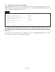
To power the unit using a DC power source, prepare a power cable using a two-conductor insulated
wire (not supplied) with a 14 AWG gauge minimum. Cut the power cable to the length required. Strip
approximately 3/8 of an inch of insulation from the power cable wires. Connect the power cables
to the standalone unit by fastening the stripped ends to the DC power connector.
Connect the power wires to the DC power source. The Power LED should indicate the presence of
power.
WARNING: Note the wire colors used in making the positive, negative and ground connections.
Use the same color assignment for the connection at the DC power source.
NOTE: If mounting with a safety ground attachment, use the safety ground screw at the rear of
the unit.
PI SA
b. When using a GX/TM SFP model, insert the SFP Fiber transceiver into the Port 1 SFP receptacle on
the GX/TM.
NOTE: The release latch of the SFP Fiber transceiver must be in the closed (up) position before
insertion.
c. Connect the UTP port via a Category 5 or better cable to a 10BASE-T, 100BASEor 1000BASE-T -TX
Ethernet device.
d. Connect the appropriate multimode or single-mode fiber cable to the fiber port of the installed module.
It is important to ensure that the transmit (Tx) is attached to the receive side of the device at the other
end and the receive (Rx) is attached to the transmit side. Single-fiber (SF) media converter models
operate in pairs. The Tx wavelength must match the Rx wavelength at the other end and the Rx
wavelength must match the Tx wavelength at the other end.
Page 11