
Datasheet

G3PJ
6
Installation and Mounting
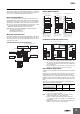
• Mount the G3PJ in the specified direction. (Refer to Mounting on
page 7.) Excessive heat generated by the G3PJ may cause short-
circuit failures of the output elements or burn damage.
• Make sure that there is no excess ambient temperature rise due to
the heat generation of the G3PJ. If the G3PJ is mounted inside a
panel, install a fan so that the interior of the panel is fully ventilated.
• Make sure the DIN track is securely mounted. Otherwise, the G3PJ
may fall.
• When mounting the heat sink, do not allow any foreign matter
between the heat sink and the mounting surface. Foreign matter
may cause malfunction due to a reduction in the heat radiation
performance.
• If the G3PJ is mounted directly in a control panel, use aluminum,
steel plating, or similar material with a low heat resistance as a
substitute for a heat sink. Using the G3PJ mounted in wood or
other material with a high heat resistance may result in fire or
burning due to heat generated by the G3PJ.
• The G3PJ is heavy. Firmly mount the DIN track and secure both
ends with End Plates for DIN-track-mounting models. When
mounting the G3PJ directly to a panel, firmly secure it to the panel.
Installation and Wiring
• Use wires that are suited to the load current. Otherwise, excessive
heat generated by the wires may cause burning.
• Do not use wires with a damaged outer covering.
Otherwise, it may result in electric shock or ground leakage.
• Do not wire any wiring in the same duct or conduit as power or
high-tension lines. Otherwise, inductive noise may damage the
G3PJ or cause it to malfunction.
• When tightening terminal screws, prevent any non-conducting
material from becoming caught between the screws and the
tightening surface. Otherwise, excessive heat generated by the
terminal may cause burning.
• Do not use the G3PJ with loose terminal screws. Otherwise,
excessive heat generated by the wire may cause burning.
• Use suitable wire lengths for wiring. Inductive noise may
occasionally cause malfunction, failure, or burn damage.
• Always turn OFF the power supply before performing wiring. Not
doing so may cause electrical shock.
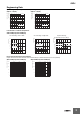
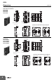
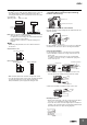
Push-in plus technology
• Do not wire anything to the release holes.
• Do not tilt or twist a flat-blade screwdriver while it is inserted into a
release hole on the terminal. The terminal may be damaged.
• Insert a flat-blade screwdriver into the release holes at an angle.
The terminal may be damaged if you insert the screwdriver straight
in.
• Do not allow the flat-blade screwdriver to fall out while it is inserted
into a release hole.
• Do not bend a wire past its natural bending radius or pull on it with
excessive force. Doing so may cause the wire disconnection.
• Do not insert more than one wire into each terminal insertion hole.
• To prevent wiring materials from smoking or ignition, use the wiring
materials given in the following table.
Note: Please use Ferrules with UL certification (R/C).
Installation and Usage
• Do not apply a voltage or current that exceeds the rating to any
terminal. Doing so may result in malfunction or burn damage.
• Select a load within the rated values. Not doing so may result in
malfunction, failure, or burning.
• Select a power supply within the rated frequencies. Not doing so
may result in malfunction, failure, or burning.
• If a surge voltage is applied to the load of the Contactor, a surge
bypass(*) will function to trigger the output element. The G3PJ
therefore cannot be used for motor loads. Doing so may result in
load motor malfunction.
* Surge Bypass
This circuit protects the output circuit from being destroyed. This
suppresses the surge energy applied inside the SSR in comparison
with a varistor for the main circuit protection. By alleviating electrical
stress on the electronic components of the SSR's output circuit,
failure and destruction due to surge voltage are suppressed.
Reference value: Surge dielectric strength of 30 kV min.
(Test conditions: 1.2
✕
50
s standard voltage waveform, peak voltage
of 30 kV, repeated 50 times according to JIS C5442)
The G3PJ in operation may cause an unexpected accident.
Therefore it is necessary to test the G3PJ under the variety of
conditions that are possible. As for the characteristics of the G3PJ, it
is necessary to consider differences in characteristics between
individual G3PJ.
The ratings in this catalog are tested values in a temperature range
between 15C and 30C, a relative humidity range between 25% and
85%, and an atmospheric pressure range between 86 and 106 kPa.
It will be necessary to provide the above conditions as well as the load
conditions if the user wants to confirm the ratings of specific SSRs.
Causes of Failure
• Tighten each terminal to the torque specified below. Improper
tightening may result in abnormal heat generation at the terminal,
which may cause burning.
• Do not supply overvoltage to the input circuits or output circuits.
Doing so may result in failure or burning.
• Do not use or store the G3PJ in the following conditions. Doing so
may result in deterioration of performance.
Locations subject to static electricity or noise
Locations subject to strong electric or magnetic fields
Locations subject to radioactivity
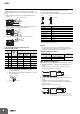
Recommended Wire
Stripping length
With Ferrules
Without Ferrules
0.25 to 1.5 mm
2
/ AWG24 to AWG16 10 mm 8 mm
Precautions for Correct Use
Terminals Screw terminal diameter Tightening torque
Input terminals M3.5 0.59 to 1.18 N·m
Output
terminals
M4 0.98 to 1.47 N·m