
Datasheet


G3PJ
7
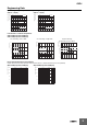
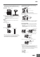
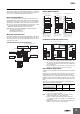
Mounting
• The G3PJ is heavy. Firmly mount the DIN Track and secure both
ends with End Plates for DIN Track mounting models. When
mounting the G3PJ directly to a panel, firmly secure it to the panel.
Screw diameter: M4
Tightening torque: 0.98 to 1.47 N·m
Note: Make sure that the load current is 50% of the rated load current
when the G3PJ is mounted horizontally.
For details on close mounting, refer to the related information
under performance characteristics.
Mount the G3PJ in a direction so that the markings read
naturally.
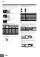
Wiring
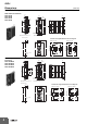
• When using crimp terminals, refer to the terminal clearances
shown below.
• Make sure that all lead wires are thick enough for the current.
• To isolate the Relay from the power supply, install an appropriate
circuit breaker between the power supply and the Relay.
Always turn OFF the power supply before wiring the Unit.
Push-in plus technology
1. Connecting Wires to the Push-in plus technology
Part Names of the technology
Connecting Wires with Ferrules and Solid Wires
Insert the solid wire or ferrule straight into the terminal until the end
strikes the terminal.
If a wire is difficult to connect because it is too thin, use a flat-blade
screwdriver in the same way as when connecting stranded wire.
Connecting Stranded Wires
Use the following procedure to connect the wires to the terminal.
1. Hold a flat-blade screwdriver at an angle and insert it into the
release hole.
The angle should be between 10° and 15°. If the flat-blade
screwdriver is inserted correctly, you will feel the spring in the
release hole respond.
2.
With the flat-blade screwdriver still inserted into the release hole,
insert the wire into the terminal hole until it strikes the terminal.
3. Remove the flat-blade screwdriver from the release hole.
Checking Connections
• After insertion, pull gently on the wire to make sure that it will not
come out (i.e., to confirm that it is held by the terminal).
• To prevent short circuits, insert the stripped part of a stranded or
solid wire or the conductive part of a ferrule until it is hidden inside
the terminal insertion hole. (See following diagram.)
Panel
Mounted on a
vertical surface
Vertical
Direction
Panel
Mounted on a
horizontal surface
10 mm
15-A and 25-A Models
Screw Terminals Push-in Terminals
12.4 mm
M4 (15 A, 25 A)
10 mm
7.0 mm
M3.5
Output Terminal Section
Input Terminal Section
Release hole
Terminal (Insertion) hole
Release hole
Terminal (Insertion) hole
Ferrule
Release hole
Flat-blade screwdriver
1
10 to 15°
Stranded Wires
2
3