New Product Switch Mode Power Supply (15/25/35/50/75/100/150/200/350-W Models) S8FS-C High Reliability at a Reasonable Cost. Reliable, Basic Power Supplies That Contribute to Stable Equipment Operation. • High Reliability: Enhanced abnormal overvoltage resistance and lightning surge resistance for stable operation even with an unstable input voltage. • Long Life: High quality electrolytic capacitor with 4 times longer life compared to previous model ensure stable quality and long life.
S8FS-C Ordering Information List of Models Note: For details on normal stock models, contact your nearest OMRON representative. Power rating Input voltage 15 W 25 W 35 W 100 to 240 VAC (allowable range: 85 to 264 VAC or 120 to 370 VDC *1) 50 W 75 W 100 W 100 to 120 VAC, 200 to 240 VAC (allowable range: 85 to 132 VAC, 176 to 264 VAC, or 248 to 373 VDC (Select with the switch.
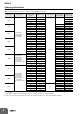
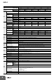
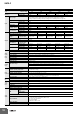
S8FS-C Ratings, Characteristics, and Functions Power rating Item Efficiency * Current * Inrush current * (for a cold start at 25) 24 V 84% typ. 85% typ. 230 VAC input 82% typ. 85% typ. 86% typ. 87% typ. Single phase 85 to 264 VAC, 120 to 370 VDC (The L terminal for the DC input is the positive side and safety standards do not apply.) (Derating is required according to the input voltage. Refer to Derating Curves on page 18.) 50 /60 Hz (47 to 450 Hz) 115 VAC input 230 VAC input 0.3 A typ. 0.
S8FS-C Power rating Item Efficiency * Inrush current * (for a cold start at 25) Output 84% typ. 85% typ. 86% typ. 86% typ. 88% typ. 88% typ. Single phase 85 to 264 VAC, 120 to 370 VDC (The L terminal for the DC input is the positive side and safety standards do not apply.) (Derating is required according to the input voltage. Refer to Derating Curves on page 18.) Additional functions 50 /60 Hz (47 to 450 Hz) 115 VAC input 0.49 A typ. 230 VAC input 0.3 A typ. --- 115 VAC input 0.10 mA 0.
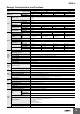
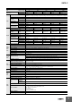
S8FS-C Power rating Item Efficiency * Inrush current * (for a cold start at 25) Output 24 V 84% typ. 87% typ. 230 VAC input 81% typ. 84% typ. 84% typ. 87% typ. Single phase 85 to 264 VAC, 120 to 370 VDC (The L terminal for the DC input is the positive side and safety standards do not apply.) (Derating is required according to the input voltage. Refer to Derating Curves on page 18.) 50 /60 Hz (47 to 450 Hz) 115 VAC input 0.66 A typ. 230 VAC input 0.41 A typ. 115 VAC input 0.15 mA 0.
S8FS-C Power rating Item Efficiency * Inrush current * (for a cold start at 25) Output Additional functions 48 V 86% typ. 87% typ. 230 VAC input 80% typ. 84% typ. 85% typ. 86% typ. 87% typ. Single phase 85 to 264 VAC, 120 to 370 VDC (The L terminal for the DC input is the positive side and safety standards do not apply.) (Derating is required according to the input voltage. Refer to Derating Curves on page 18.) 50 /60 Hz (47 to 450 Hz) 115 VAC input 0.97 A typ. 230 VAC input 0.59 A typ.
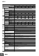
S8FS-C Power rating Item Efficiency * Inrush current * (for a cold start at 25) Output 87% typ. 230 VAC input 77% typ. 83% typ. 84% typ. 87% typ. 87% typ. Single phase 85 to 264 VAC, 120 to 370 VDC (The L terminal for the DC input is the positive side and safety standards do not apply.) (Derating is required according to the input voltage. Refer to Derating Curves on page 18.) 50 /60 Hz (47 to 450 Hz) 115 VAC input 230 VAC input 1.4 A typ. 0.83 A typ. --- 115 VAC input 0.25 mA 0.25 mA 0.
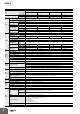
S8FS-C Power rating Item Efficiency * Current * Inrush current * (for a cold start at 25) Additional functions 36 V 48 V 85% typ. 86% typ. 87% typ. 230 VAC input 81% typ. 83% typ. 84% typ. 87% typ. 87% typ. 88% typ. Single phase 85 to 132 VAC, 176 to 264 VAC, 248 to 373 VDC Select with the switch. (The L terminal for the DC input is the positive side and safety standards do not apply.) (Derating is required according to the input voltage. Refer to Derating Curves on page 18.
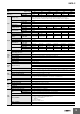
S8FS-C Power rating Item Efficiency * Current * Inrush current * (for a cold start at 25) 24 V 36 V 48 V 85% typ. 86% typ. 86% typ. 87% typ. 230 VAC input 82% typ. 85% typ. 86% typ. 87% typ. 87% typ. 88% typ. Single phase 90 to 132 VAC , Single phase 180 to 264 VAC , 254 to 373 VDC Select with the switch. (The L terminal for the DC input is the positive side and safety standards do not apply.) (Derating is required according to the input voltage. Refer to Derating Curves on page 18.
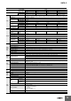
S8FS-C Power rating Item Efficiency * Current * Inrush current * (for a cold start at 25) 36 V 48 V 88% typ. 89% typ. 88% typ. 230 VAC input 81% typ. 87% typ. 88% typ. 90% typ. 90% typ. Single phase 90 to 132 VAC , Single phase 180 to 264 VAC , 254 to 373 VDC Select with the switch. (The L terminal for the DC input is the positive side and safety standards do not apply.) (Derating is required according to the input voltage. Refer to Derating Curves on page 18.
S8FS-C Power rating Item Efficiency * Current * Inrush current * (for a cold start at 25) 36 V 48 V 86% typ. 87% typ. 87% typ. 230 VAC input 78% typ. 85% typ. 88% typ. 88% typ. 88% typ. Single phase 90 to 132 VAC , Single phase 180 to 264 VAC , 254 to 373 VDC Select with the switch. (The L terminal for the DC input is the positive side and safety standards do not apply.) (Derating is required according to the input voltage. Refer to Derating Curves on page 18.
S8FS-C Conditions Efficiency The value is given for the rated output voltage and rated output current. Although some inverters give 50/60 Hz as the output frequency, do not use an inverter output as the power source for the Power Supply. Doing so may result in smoking or burning due to internal temperature increases in the Power Supply. If you connect a UPS to the input, do not connect one with a square wave output.
S8FS-C Connections Block Diagrams S8FS-C015J (15 W) Fuse: 3.15 A AC (L) +V Noise filter Input DC output −V AC (N) Inrush current protection Rectifier Smoothing circuit Rectifier/ smoothing circuit Drive control circuit Overcurrent detection Voltage detection Photocoupler Overvoltage detection S8FS-C025 (25 W) S8FS-C035 (35 W) S8FS-C050 (50 W) S8FS-C075 (75 W) Fuse 25 W: 4 A 35 W: 3.
S8FS-C S8FS-C10005 (100 W) S8FS-C150 (150 W) Fuse: 5A Rectifier/ smoothing circuit AC (L) +V Noise filter Input DC output −V AC (N) Inrush current protection Input voltage selector switch 100 to 120 VAC/ 200 to 240 VAC switching Rectifier/ smoothing circuit Drive control circuit Overcurrent detection Voltage detection Overvoltage detection Photocoupler S8FS-C200 (200 W) Rectifier/ smoothing circuit Fuse: 8A AC (L) +V Noise filter Input DC output −V AC (N) Input voltage selector s
S8FS-C S8FS-C35024 (350 W) Rectifier/ smoothing circuit Fuse: 10 A AC (L) +V Noise filter Input DC output −V AC (N) Inrush current protection Input voltage selector switch 100 to 120 VAC/ 200 to 240 VAC switching Rectifier/ smoothing circuit Fan Drive control circuit Overcurrent detection Voltage detection Overvoltage detection Photocoupler Overheating detection S8FS-C35005 (350 W) S8FS-C35012 (350 W) S8FS-C35036 (350 W) S8FS-C35048 (350 W) Fan Rectifier/ smoothing circuit Fuse: 10 A AC
S8FS-C Construction and Nomenclature Nomenclature 15-W Models 25-W, 35-W, 50-W, and 75-W Models 100-W and 150-W Models 4 5 1 2 S8FS-C025 S8FS-C035 1 3 2 1 3 1 2 3 S8FS-C050J S8FS-C075J 3 3 6 2 6 3 3 2 S8FS-C200J S8FS-C350J S8FS-C100J S8FS-C150J 6 No. Name Function Connect the input lines to these terminals. *1 1 Input terminals (L), (N) 2 Protective Earth Terminal (PE) Connect the ground line to this terminal.
S8FS-C Engineering Data Derating Curves Derating for Ambient Temperatures Power rating Output voltage 15 W 5V 25 W 35 W 50 W (2) 12 V (1) 15 V (1) (1) (1) 75 W 100 W 150 W (3) (4) (5) (1) (2) 36 V --- --- --- --- --- 48 V --- --- --- (1) (1) 90 80 110 100 90 80 70 60 50 50 50 40 40 40 30 30 30 20 20 20 10 10 10 0 −30 −20 −10 0 −30 −20 −10 10 20 30 40 50 60 70 80 Ambient temperature (°C) 0 Load ratio (%) 110 100 90 80 80 70 60 60 50 50 50 40 40
S8FS-C Derating for Input Voltages Power rating Output voltage 15 W 25 W 35 W 50 W 75 W (8) (8) (8) (8) (8) 100 W 150 W 5V 12 V 15 V (9) (10) 24 V 36 V --- --- --- --- --- 48 V --- --- --- (8) (8) 100 90 80 90 80 60 50 40 40 40 30 30 30 20 20 20 10 10 10 0 85 205 235 265 Input voltage (Vac) 95 105 115 80 (13) 110 Load ratio (%) 90 100 90 80 110 100 90 80 70 70 70 60 60 60 50 50 50 40 40 40 30 30 30 20 20 20 10 10 10 0 90 100 110 12
S8FS-C Overload Protection Output voltage (V) The load and the Power Supply are automatically protected from short-circuit currents and overcurrent damage by this function. Overload protection is activated if the output current rises above 105% of the rated current. When the output current returns within the rated range, the overload protection is automatically cleared. Intermittent operation 0 50 100 Output current (%) The values shown in the above diagrams are for reference only. Note: 1.
S8FS-C Dimensions (Unit: mm) Power Supplies Models with Terminal Block Facing Upward S8FS-C025 (25 W) 20.5 55±0.5 Panel mounting hole dimensions 8.16 Using the mounting holes in the Power Supply 3.5 9.5 82±1 Bottom: Two, M3 (Depth: 5 mm max.) 40±0.5 40.5 Five, M3.5 Using the screw holes in the Power Supply Two, M3 Two, 3.5 dia. Bottom mounting 40±0.5 55±0.5 88.5±0.5 3.5 dia. 88.5±0.5 99±1 5 5 Side mounting Two, M3 Two, 3.5 dia. 74±0.5 87±0.5 6.5 87±0.5 3.5 3.5 dia. 17.
S8FS-C S8FS-C075 (75 W) S8FS-C100 (100 W) 24 78±0.5 Panel mounting hole dimensions 8.16 Using the mounting holes in the Power Supply 3.5 9.5 Bottom: Two, M3 (Depth: 5 mm max.) Using the screw holes in the Power Supply 97±1 84.5±0.5 Seven, M3.5 Bottom mounting 32 Two, 3.5 dia. Two, M3 84.5±0.5 78±0.5 152.5±0.5 3.5 dia. Three, M3 4.5 152.5±0.5 5.5 159±1 Side mounting 150±0.5 Three, 3.5 dia. 9.5±0.5 13±0.5 18±0.5 117±0.5 Side: Three, M3 (Depth: 6 mm max.) 6.5 18±0.5 150±0.
S8FS-C S8FS-C200 (200 W) 32.5 Panel mounting hole dimensions 150±0.5 Using the screw holes in the Power Supply 8.16 Four, 4.5 dia. 9.5 112.5±1 Bottom mounting 50±0.5 50±0.5 150±0.5 Four, 4.5 dia. Side mounting 30 25±0.5 150±0.5 Nine, M3.5 Bottom: Four, M4 (Depth: 5 mm max.) 32.5 212±1 150±0.5 25±0.5 Side: Four, M4 (Depth: 6 mm max.) 50±1 (12.5) S8FS-C350 (350 W) 32.5 Panel mounting hole dimensions 150±0.5 41.5 8.16 Using the screw holes in the Power Supply 34.1 Four, 4.5 dia.
S8FS-C Models with Terminal Block Facing Forward S8FS-C015J (15 W) Panel mounting hole dimensions Using the screw holes in the Power Supply 51±1 25.4 Two, 3.5 dia. Bottom mounting Bottom: Two, M3 (Depth: 4 mm max.) 55±0.5 12.5 55±0.5 Two, 3.5 dia. 14 max. Side mounting 78±1 66.5±0.5 28±1 14 6 7.62 Five, M3 66.5±0.5 8.75 Side: Two, M3 (Depth: 3 mm max.) S8FS-C025J (25 W) (12) 20.5 Panel mounting hole dimensions 55±0.5 Bottom: Two, M3 (Depth: 5 mm max.
S8FS-C S8FS-C050J (50 W) Bottom: Two, M3 (Depth: 5 mm max.) (12) 78 Panel mounting hole dimensions 3.5 Using the mounting holes in the Power Supply 85.5±0.5 97±1 33±0.5 Using the screw holes in the Power Supply Two, 3.5 dia. Bottom mounting 33 3.5 dia. Two, M3 85.5±0.5 33±0.5 122.5±0.5 122.5±0.5 129±1 4.5 6.5 120±0.5 3.5 dia. 28.5 8.2 9.5 18±0.5 32 ±0.5 Three, 3.5 dia. 18 Three, M3 Side mounting 120±0.5 13±0.5 9±0.5 77 10 Side: Three, M3 (Depth: 6 mm max.) ±0.5 (12) 24 78±0.
S8FS-C S8FS-C200J (200 W) Panel mounting hole dimensions 32.5 150±0.5 Using the screw holes in the Power Supply Four, 4.5 dia. Bottom mounting 50±0.5 112.5±1 150±0.5 50±0.5 Four, 4.5 dia. Side mounting 25±0.5 150±0.5 30 Bottom: Four, M4 (Depth: 5 mm max.) (12) 32.5 212±1 150±0.5 25±0.5 50±1 (12.5) 8.2 9.5 Nine, M3.5 Side: Four, M4 (Depth: 6 mm max.) S8FS-C350J (350 W) Panel mounting hole dimensions 32.5 150±0.5 41.5 Using the screw holes in the Power Supply 34.1 Four, 4.5 dia.
S8FS-C Mounting Brackets (Order Separately) Power rating Mounting direction Model 15 W S82Y-FSC015DIN 25 W S82Y-FSC025DIN 35 W S82Y-FSC050DIN 50 W 75 W DIN Rail 100 W S82Y-FSC150DIN 150 W 200 W S82Y-FSC350DIN 350 W 15 W S82Y-FSC015DIN-S 25 W S82Y-FSC025DIN-S 35 W 50 W S82Y-FSC035DIN-S Bottom-mounting to DIN Rail S82Y-FSC050DIN-S 75 W S82Y-FSC100DIN-S 100 W 150 W 200 W 350 W S82Y-FSC150DIN-S Bottom-mounting with L-brackets S82Y-FSC350B (4 brackets) S82Y-FSC015DIN Mounting Method (1
S8FS-C S82Y-FSC050DIN (12) Mounting Method 147.7 (12) 117.7 50W 35W 5 3.5 dia. (35W) 48.5 49.5 85.5±1 48.5 50W 4.5 (Sliding: 7.2 max.) 5.5 (Sliding: 8.2 max.) 35W 50W 3.5 dia. (50W) 47.5 Accessories (2 locations) Be sure to use the accessory screws. Mounting screw tightening torque: 0.48 to 0.59 N·m for M3 screws 35W 39.2 37.2 35.2±1 112.5±1 5 max. S82Y-FSC150DIN Mounting Method (12) 75W/100W 150W 217.7 5 177.7 (12) 47.9 49.1 98.5±1 Four, 3.5 dia. 150W 3.9 (Sliding: 6.6 max.
S8FS-C S82Y-FSC015DIN-S Mounting Method 38.7 5 Two, 3.5 dia. 25.5 53±1 25.5 4.5 (Sliding: 7.2 max.) 43.2±1 Accessories (2 locations) Be sure to use the accessory screws. Mounting screw tightening torque: 0.48 to 0.59 N·m for M3 screws 47.2 79.5±1 87.2 (13) S82Y-FSC025DIN-S 5 Mounting Method 45.7 32.5 Two, 3.5 dia. 78.5±1 49.5 3.5 (Sliding: 6.2 max.) 49.7±1 (12) 98±1 108.2 Accessories (2 locations) Be sure to use the accessory screws. Mounting screw tightening torque: 0.48 to 0.
S8FS-C S82Y-FSC050DIN-S Mounting Method 48.7 5 Two, 3.5 dia. 48.5 85.5±1 48.5 4.5 (Sliding: 7.2 max.) Accessories (2 locations) Be sure to use the accessory screws. Mounting screw tightening torque: 0.48 to 0.59 N·m for M3 screws 49.7±1 80.2 98±1 138.2 (12) S82Y-FSC100DIN-S 5 48.7 Four, 3.5 dia. 75W/100W Mounting Method 47.9 98.5±1 49.1 3.9 (Sliding: 6.6 max.) 51.2±1 (12) 151±1 168.2 Accessories (4 locations) Be sure to use the accessory screws. Mounting screw tightening torque: 0.
S8FS-C S82Y-FSC350B (Four Brackets) Mounting Method (R2.2) 11.25 2 15±1 4.4 16.25 6.5 4.5 dia. 19.5±1 12.5 18.05±1 Panel mounting hole dimensions Four, M4 150±0.5 135 145 150 30 135±0.5 Accessories (4 locations) Be sure to use the accessory screws. Mounting screw tightening torque: 1.08 to 1.32 N·m for M4 screws Note: The mounting bracket is available in 200-W and 350-W models. The figure shows a 350-W Power Supply.
S8FS-C For Users of S8JC DIN Rail-mounting Power Supplies If you are using a DIN Rail-mounting S8JC-series Power Supply, you can replace it with an S8FS-C-series Power Supply with Forward-facing Terminal Block and a DIN Rail Mounting Bracket.
S8FS-C DIN Rail (Order Separately) Note: All units are in millimeters unless otherwise indicated. Mounting Rail (Material: Aluminum) 7.3±0.15 4.5 27±0.15 35±0.3 Model PFP-100N 15 25 10 25 25 1,000 (500)* 10 25 15 (5)* PFP-50N 1 * Value in parentheses are for PFP-50N. Mounting Rail (Material: Aluminum) 16 4.5 Model 35±0.3 27 15 25 25 10 25 1,000 10 25 End Plate 24 15 29.2 1 PFP-100N2 1.5 10 6.2 M4 × 8 panhead screw 1.8 Model 1 50 1.8 35.5 35.5 PFP-M 11.
S8FS-C Safety Precautions Refer to Safety Precautions for All Power Supplies. Warning Indications CAUTION Indicates a potentially hazardous situation which, if not avoided, may result in minor or moderate injury or in property damage. Precautions for Supplementary comments on what to do or avoid doing, to use the product safely.
S8FS-C Mounting Wiring The standard mounting pattern is shown below. Mounting Pattern A *1 *1 75 mm min. 20 mm min. The above figure shows a model with the terminal block facing upward. Mounting Pattern B Connect the ground completely. A protective earthing terminal stipulated in safety standards is used. Electric shock or malfunction may occur if the ground is not connected completely. Minor fire may possibly occur. Ensure that input and output terminals are wired correctly.
S8FS-C Output Voltage Adjuster (V. ADJ) Parallel Operation The output voltage adjuster (V. ADJ) may possibly be damaged if it is turned with unnecessary force. Do not turn the adjuster with excessive force. After completing output voltage adjustment, be sure that the output capacity or output current does not exceed the rated output capacity or rated output current. Parallel operation is not possible.
S8FS-C In Case There Is No Output Voltage There is a possibility that functions such as overcurrent protection, over-voltage protection or overheating protection are functioning. The internal protection circuit may operate if a large amount of surge voltage such as a lightening surge occurs while turning ON the Power Supply.
Terms and Conditions Agreement Read and understand this catalog. Please read and understand this catalog before purchasing the products. Please consult your OMRON representative if you have any questions or comments. Warranties. (a) Exclusive Warranty. Omron’s exclusive warranty is that the Products will be free from defects in materials and workmanship for a period of twelve months from the date of sale by Omron (or such other period expressed in writing by Omron).
OMRON Corporation Industrial Automation Company Authorized Distributor: Kyoto, JAPAN Contact: www.ia.omron.com Regional Headquarters OMRON EUROPE B.V. Wegalaan 67-69, 2132 JD Hoofddorp The Netherlands Tel: (31)2356-81-300/Fax: (31)2356-81-388 OMRON ELECTRONICS LLC 2895 Greenspoint Parkway, Suite 200 Hoffman Estates, IL 60169 U.S.A. Tel: (1) 847-843-7900/Fax: (1) 847-843-7787 OMRON ASIA PACIFIC PTE. LTD. No.