
Controller Link Units Operation Manual


92
CJ-series Controller Link Units Section 4-2
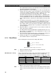
6. Only node addresses 1 through 32 can be used on networks for which 62
nodes have not been enabled.
7. The Wired Network 62 Node Enable Bit in the DM Parameter Area soft-
ware switches of CS1W-CLK21-V1 and CJ1W-CLK21-V1 Units is read
when the Unit is restarted.
8. The send sequence for the data link areas is determined according to the
sequence of node addresses for automatically set data links.
9. Assign node addresses consecutively beginning from 01 whenever possi-
ble to minimize Network construction time.
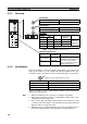
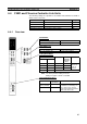
4-2-4 Baud Rates
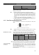
Set the following pins for the baud rate settings (DIP switch).
Note Always turn OFF the PLC’s power before setting the baud rate.
Baud Rate (Pins 1 and 2) Set the same baud rate for all the nodes on the Network using DIP switch pins
1 and 2 on the front of the Unit. The baud rate is set as shown below.
The maximum transmission distance will also change according to the setting.
Note The factory default setting is shown in bold.
Note 1. Set the same baud rate for all the nodes on the Network. Normal commu-
nication cannot be performed unless the same baud rate is set for all the
nodes.
2. The default setting is 2 Mbps, 500 m.
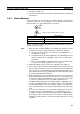
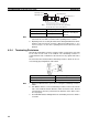
4-2-5 Terminating Resistance
Turn ON the terminating resistance using the switch on the bottom of the Unit
for the Units of both ends of the Network. The terminating resistance is
required at both ends of a Network to absorb unnecessary signals and reduce
noise.
The Controller Link Unit has built-in terminating resistance, which can be con-
nected simply by turning ON the slide switch.
ON
ON
1
2
Note: The factory default settings are shown.
Pins 1, 2: Baud rate
Pins Baud rate Maximum
transmission distance
Pin 1 Pin 2
OFF OFF 2 Mbps 500 m
ON OFF 1 Mbps 800 m
OFF ON 500 Kbps 1 km
ON ON Do not set.
Bottom switch Terminating resistance
OFF (factory default) Not connected.
ON Connected.
↓
ON