
Controller Link Units Operation Manual


93
C200HX/HG/HE Controller Link Units Section 4-3
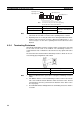
Note 1. Always turn OFF the PLC’s power before setting the terminating resistance
switch.
2. Turn ON the switch to connect terminating resistance at the nodes at both
ends of the Network and turn OFF the switch at all other nodes. Normal
communication cannot be performed in the Network unless all the nodes
are set properly.
3. The TER LED indicator will light when the terminating resistance switch is
set to ON.
4. The default setting is OFF (not connected).
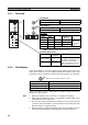
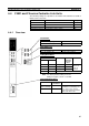
4-3 C200HX/HG/HE Controller Link Units
The following settings are required for a Controller Link Unit used with a
C200HX/HG/HE PLC.
Item Switch Page
Node address Node address switches 94
Baud rate Baud rate and operating level switch, pins 1
and 2
95
Operating level Baud rate and operating level switch, pin 4) 95
Terminating resistance Terminating resistance switch 96