
Controller Link Units Operation Manual


151
Setting Data Links Section 5-2
Note a) The total number of words in data link send and receive areas
must not exceed 8,000 per node.
b) The following values must be satisfied for each node for the data
link area 1 and area 2 so that the final word in the data link does
not go beyond the last word in the PLC memory area.
(Data link start word – 1) + Total number of send/receive
words in area
≤ 247 (IR Area)
63 (LR Area)
5999 (DM Area)
6143(EM Area)
c) When using area 1 only, set the data link start word, type, and
the number of send words of area 2 to 0.
d) When using area 2 only, set the data link start word, type, and
the number of send words of area 1 to 0.
e) The startup node must be registered as a participating node of
the data links. If not, the data links will not start.
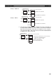
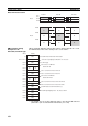
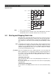
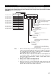
5-2-5 Automatic Setting Example
This section shows an example of DM Parameter Area settings and the data
link areas that are created as a result.
DM Parameter Area
Settings for Equality
Layout
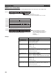
Set the parameters in the startup node as follows:
First data link status word Set in BCD the first word used for storing data link status.
An area of 16 words is used for storing status.
0 (*) or IR 001 to IR 232
Status is stored in the IR or CIO Area only.
*: When 0 is set, the status for nodes 1 to 6 is stored in
IR 91 to IR 93.
Nodes participating in the
data links
Set to ON (1) the bits corresponding to the nodes partici-
pating in the data links.
The data link will not start unless the startup node itself is
set as participating node.
The data link will not start if the node is set to a parameter
exceeding the “maximum node address” of the network
parameter.
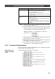
Item Setting range
Data link mode: Automatic
First data link status word: IR 310
Participating nodes: #1, #2, and #3
Area 1 data link start word: LR 00
Number of words: 10
Area 2 data link start word: DM 1000
Number of words: 200