
Controller Link Units Operation Manual


191
Using the Message Service Section 6-3
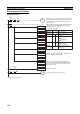
SEND/RECV Flag Operations
• The Network Instruction Enabled Flag turns OFF during transmission or
reception, and ON after the data transmission or reception has been com-
pleted (regardless of whether an error occurs).
• The Network Instruction Error Flag retains its status until the next data
transmission or reception.
• Even when there is an abnormal end, the Network Instruction Error Flag
turns OFF when the next communications instruction is executed.
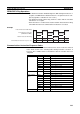
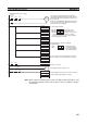
Example
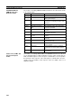
Communications Instruction Response Codes
The status after a communications instruction has been executed is reflected
in the words shown in the following table. During instruction execution, it
becomes “00” or “0000,” and it is reflected here after the execution has been
completed.
Network Instruction Enabled Flag
Communications instruction
(SEND/RECV/CMND)
Network Instruction Error Flag
Communications instruction response code
Instruction 2
being executed
Instruction 3
being executed
Previous
end
1
0
1
0
Instruction 1
being executed
00 00 00 0004
00
(Normal
end)
(Normal
end)
(Busy)
PLC Word Bits Contents
CS/CJ-series A203 --- Port 0 response code
A204 --- Port 1 response code
A205 --- Port 2 response code
A206 --- Port 3 response code
A207 --- Port 4 response code
A208 --- Port 5 response code
A209 --- Port 6 response code
A210 --- Port 7 response code
C200HX/HG/HE SR 237 08 to 15 Operating level 1 response code
00 to 07 Operating level 0 response code
CVM1 and CV-
series
A503 --- Port 0 response code
A504 --- Port 1 response code
A505 --- Port 2 response code
A506 --- Port 3 response code
A507 --- Port 4 response code
A508 --- Port 5 response code
A509 --- Port 6 response code
A510 --- Port 7 response code
CQM1H-series AR 02 00 to 07 Response code